Spring 2017 Velociraptor: Final Assembly Update
Authors
By: Andrea Lamore (Manufacturing)
Approved By: Jesus Enriquez (Project Manager)
Table of Contents
Introduction
Assembly of the first velociraptor demonstrated some problems that were not clear from the SolidWorks model alone. These problems included a wobbliness/loose motion of the legs, the hip joint was arching when it should have been straight, and the head and tail were bending and lacked stability. In order to increase the stability of the velociraptor I made some changes to the design.
Requirement L1-3: The Robot should resemble the embodiment of a Velociraptor
Body
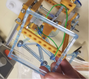
Assembly of the first velociraptor demonstrated some problems that were not clear from the SolidWorks model alone. These problems included a wobbliness/loose motion of the legs, the hip joint was arching when it should have been straight, and the head and tail were bending and lacked stability. In order to increase the stability of the velociraptor I made some changes to the design.
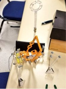
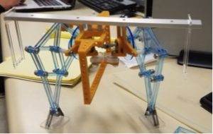
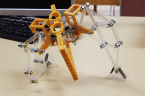
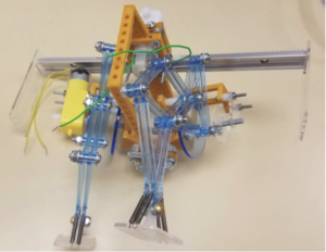
Above, on the first assembly, you can see the head and tail that will now be used only aesthetically. Below is the second Assembly with no electronics attached.
I increased the width of the hip socket so the u-joint wouldn’t bend vertically. Two ball bearing were to be used on each side.
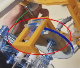
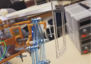
I added stabilizers to the leg so the circle would remain vertical. I also cut the circle large enough to reach the stabilizers without interfering with the shaft motion.
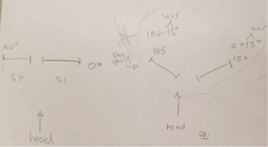
A single servo should be able to move the hips, however 2 servos will be attached and move in sync to increase torque. This requires that they be attached at 90 degrees then move plus and minus 15 degrees respectively depending on whether the legs are turning out or in.
I used thicker acrylic sheeting for the new leg cuts and reduced the size of the shaft holes to the minimum size that could fit a 6-32 screw (which I used for the shaft).
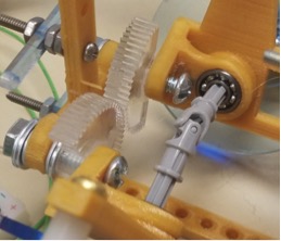
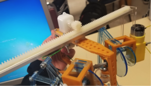
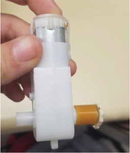
I replaced the head and the tail mechanism with a rack and pinion on a linear bearing. This mechanism requires a DC motor instead of two servos. The DC motors will send feedback from the rotary encoders to indicate how many turns and at what angle the rack positioned at. The DC motor moves the shaft back and forth to adjust the Velociraptors center of gravity. At the end of the shafts are counter weight holders that hang low to the ground to lower the center of gravity and increase balance.
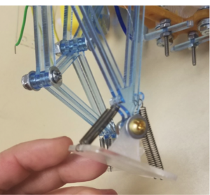
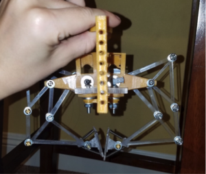
I found the foot mechanism to be somewhat successful in maintaining the stability of the velociraptor while it walks, however, the more weight I added to the velociraptor (DC motors, rack and pinion, etc.), the more resistance I required from the springs. Later I plan to double the amount of springs in the feet.
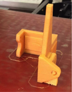
I printed some feet and ordered some rubber. I will eventually glue the rubber to the larger foot platforms and attach them to the raptor. The raptor can stand on rubber far better than it can stand on a smooth surface such as tile or plastic flooring. The velociraptor is shown slipping in the following image. He caught himself by landing on his knee.
Although I decreased the hole size for the 6-32 screw shaft to the minimum there is still some wiggle room in the legs. When You laser cut it actually cuts a little larger than expected (Contrary to 3D printing). If I could cut again I’d reduce the hole size a little more since the legs still have some wobble due to the wiggle room in the shaft holes.
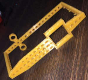
I cut some squares that will eventually be used to mount the 3Dot board and the PCB.
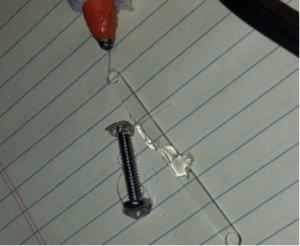
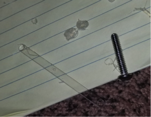
I used hot glue in place of super glue or screws since it is easy to peel off if needed. Hot glue was surprisingly useful for temporary fastening of parts, especially parts that don’t have easy compatibility such as DC motors and Servos. Hot glue caused no damage to these parts after being peeled off. I tested this in the following before and after images.
The turning mechanism was successful as can be observed from the following pictures.
The hips can be turned up to 90 degrees outward on each side. When the legs open the shaft connected to the u-joints and legs slide inward. The more the legs open the more room the shaft needs to be able to slide inward. All of this needed to be taken in to account in order to prevent interference of parts.
Conclusion
The new velociraptor is far less wobbly then the first. The hip mechanism, foot mechanism and the new head and tail mechanism work successful. The only thing I would change is the leg mechanism so that it’s sturdier and less wobbly.

