Spring 2017 Velociraptor: First SolidWorks Model
Authors
By: Andrea Lamore (Manufacturing)
Approved By: Jesus Enriquez (Project Manager)
Table of Contents
Introduction
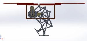
During the early stages of the design process, leading up to PDR, the Velociraptor’s frame was similar to what was presented at CDR but had a few distinct differences in terms of specific part modification and part sizes. The purpose of this post is to present one of the first iterative designs for the Spring 2017 Velociraptor.
3D Modeling on SolidWorks
When first designing the hardware model for the Velociraptor, a design change was made so the Velociraptor could be made to walk with 2 DC motors. The Theo Jansen Linkage allows for walking with continuous rotation around a jingle joint, making it an ideal choice for the Velociraptor leg design.
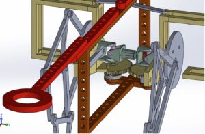
The Velociraptor requires a turning mechanism. This could be done most obviously by having one leg take steps while pivoting around the other leg (much like how an RC car turns), or my adding an axis of rotation around one of the joints in the leg (either the hip or the ankle in our cases). Two universal joints at the hip was chosen to provide rotation at the top of the leg mechanism. This allows the continuos rotation of the leg while the hip is at an angle.
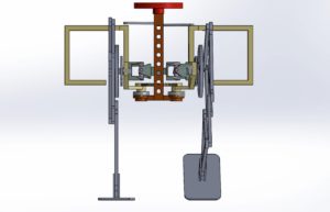
The DC motor will be placed on the outside of the leg as to help with balance of the robot by moving mass away from the center axis so that shifting the center of mass (done by shifting the head and the tail) may be accomplished more easily. This also allows the motors to stay in parallel with the leg when the hip rotates.
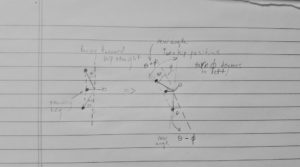
When the velociraptor turns, the center of mass will move away from over the fulcrum point, for that reason two servos will control the head and tail independently. This was decided so that when the velociraptor turns, the head can be adjusted separate from the tail so that the center of mass stays over the fulcrum pint (over the standing foot). The following figure demonstrated how the center of mass changes with rotation of the hip.
Conclusion
As the iterative design process was pushed forward, through prototyping and trial & error, it led to further design changes leading up to our CDR design model. Realizing as oppose to modeling on SolidWorks is much more difficult and that was discovered through experience in assembly the physically manufactured parts for the Velociraptor.


