Spring 2017 Velociraptor: Robot Assembly Process
Authors
By: Andrea Lamore (Manufacturing)
– Assembly Process
Edited & Approved By: Jesus Enriquez (Project Manager)
– Introduction & Conclusion
Table of Contents
Introduction
Before going into Critical Design Review, our team had to assemble the Velociraptor in order to have it Demo ready. Prior to PDR, we had a design in mind which was modeled on SolidWorks which continued to change as we approached CDR and we went through the engineering design process making iterative changes through the weeks between the two presentations. This post covers some of the thinking and planning that went through our minds as the Velociraptor was being assembled throughout the weeks.
Assembly Process
Assembling the Velociraptor resulted in minor changes to the original design. The legs were made up of several linkages. Screws and locknuts were used as the shaft. Lining up the linkages so that every piece was parallel with the other was key in eliminating the wobbliness of the leg and smoothing out the steps.
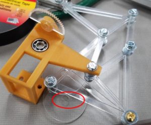
I decided to laser cut the flat parts to ensure the dimensions were accurate and the linkages came out smooth. The circle shaped shaft that connects to the motor needed to be re-cut so the there was a tighter fit between the motor shaft and the leg rotation shaft. The smoothness of the “step” is key in getting the velociraptor walking without falling. Below I circled the hip shaft and what part needed to be re-cut.
Note: The primary tools used were a wrench and needle nose pliers.
Figure 1: Modified Circular Shaft
The servo holder was too delicate and bulky. I ended up laser cutting a part that would replace the 3D printed servo holder. The following shows previous and new design for the servo holder.
Figure 2: Original Servo Holder Design
Figure 3: New Servo Holder Design
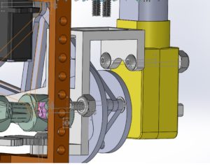
The hip of the velociraptor was too long and was just barely hitting the leg shaft on each rotation making the steps wobbly. I had the option of sawing the hip shorter or reprinting it and decided to reprint it. The following image shows the new hip and SolidWorks verified the new part would not hit the leg shaft.
Figure 4: SolidWorks Model of New Hip-Design Assembly
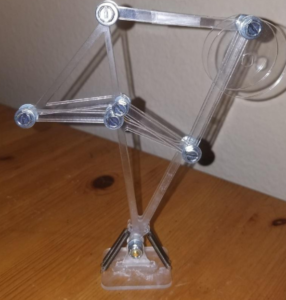
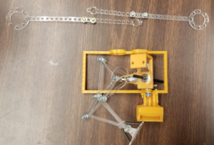
The feet were laser-cut and super-glued together using “gel” super glue. The resulting hold was very strong and in the future I will try to laser-cut as many parts as possible and super-glue them together instead of 3D printing. The spring mechanism for the foot worked as planned. A little groove was cut into the spring slot so that the spring would not easily slip out of place. The following image shows Left-leg waiting patiently while Right-leg is assembled.
Figure 5: Laser-Cut Version for Velociraptor Legs
The following 3 image demonstrate how the foot bends at the ankle using the springs:
Figure 6: New laser-cut Velociraptor Ankle/Foot Design
The head and tail radius, as well as the dummy-weights on the end were adjusted until the velociraptor could stand without tipping over. In the future, as we add the micro-controller and other components, the velociraptor’s head and tail radius as well as the angle of head and tail rotation need to be calibrated with each change in structure.
The gears for the turning mechanism worked well but were recut using thicker plastic to ensure they do not slip when the velociraptor is walking.
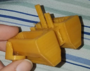
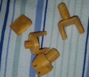
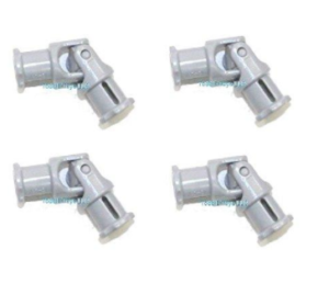
The u-joints were originally 3D printed but came out unusable. Lego U-joints and shafts were ordered to be used instead. They worked marvelously. The following images show the 3d printed u-Joints and the Lego u-connects.
Figure 7: Original 3D printed Universal Joints
Figure 8: Lego Universal Joints to replace original U-Joints
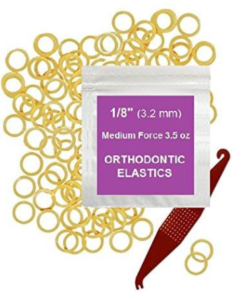
The leg shaft and dc motor shafts are not threaded so a screw could not be used as a cap. Instead little rubber bands were used to cap them and prevent slipping-out.
Figure 9: Rubber bands used to cap the screws
For the sake of simplifying the code to come, the group decided one DC motor would be used instead of two. The legs had to be moved 180 degrees out of phase with one another before being locked into place. It was easy to calibrate this since the shaft can only be rotated in increments of 90 degrees to ensure a proper fit.
Figure 10: DC Motor Shaft Design
Figure 10: Velociraptor Assembly before CDR
Conclusion
During hardware design changes, we noticed that the original design was a lot more bulky, making it over all heavier and it also became more challenging to get the robot to walk, let alone standing. Our Manufacturing continued to strip parts away and simplified the design to give it a cleaner and tighter look which also allowed the robot to move more functionally. The final design can be reference to in the final blog post for the Spring 2017 Velociraptor.
References
- https://www.amazon.com/Technic-U-Joint-Mindstorms-Universal-Joint/dp/B01IKRCU7K/ref=sr_1_1?s=toys-and-games&ie=UTF8&qid=1492407338&sr=1-1&keywords=lego+u+joint
- https://www.amazon.com/gp/product/B00OT8QWLK/ref=oh_aui_detailpage_o00_s00?ie=UTF8&th=1
- https://www.123rf.com/photo_19111999_assembling-a-robot.html

