Spring 2017 Velociraptor: Schematic, PCB, and Construction
Authors
By: Andrea Lamore (Manufacturing)
Edited & Approved By: Jesus Enriquez (Project Manager)
Table of Contents
Introduction
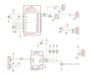
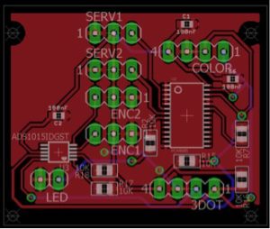
We had to build a custom PCB. Our PCB contained a 12 channel PWM expander the communicated with the peripheral devices that the 3Dot board did not have pinouts to hold. It was important to make sure everything on the PCB was I2C compatible so that the 3Dot board could communicate with it via only 2 pins. Netted to the PWM expander is an LED, potentially 3 servos, a color sensor, 2 rotary encoders, and an A2D converter for the rotary encoders.
Requirement L1-5: The Velociraptor shall use a custom PCB
Body
Below is the schematic and the PCB design
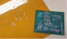
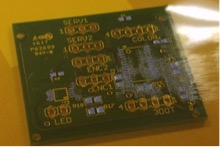
The Board we ordered and the stencil
Surface mount soldering.
Solder pasts is layered over the stencil on to the PCB and then heated in the oven. Before laying out paste the stencil and PCB need to be secured with tape. After the paste is spread flat over the stensil with a credit card the stencil and the tape can be peeled off. The parts I was working with were about the size of a grain of rice, this is a reasonable size if one is hand placing parts. However, one of the capacitors I had to lay over the PCB was the size of a grain of sand, in these instances it makes more sense to use a Pick-and-place. If you do not have access to a pick and place make sure you are aware of the sized components you are ordering.
After the parts are placed over the solder, the board can be placed in the oven until the solder turns a shiny metallic color.
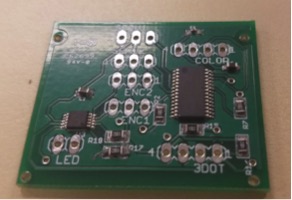
With Unheated Paste and Components
Note that is soldering you PCB with paste is not something to guess at. Soldering the PCB requires a lot of visual observation and attention to detail. You must use your best judgment to ensure that there are no shorts after heating up you board. Most of the teams fail the first time because they treat soldering the PCB more like a step-by-step procedure rather than an art.
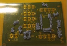
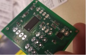
After placing PCB in Toaster oven for a couple minutes
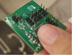
After I attached the through-hole components with a solder iron.
Conclusion
If I could redo the PCB I’d collaborate more with the EnC so that the parts ordered are a reasonable size so that they could be easily hand soldered onto the board. I’d add a more complicated display to the PCB (probably 2 seven segment displays) and more LEDs. I’d use an LED instead of a header. I’d use screw clamps for the power supply instead of a headers- since they hold easier. I’d include some control buttons/switches so I could potentially program various setting for the Velociraptor and change them easily by adjusting the switches on the PCB and resetting the board with a push button.

