By: Mesfer Aldosari
Mesfer Aldosari
System Block Diagram:
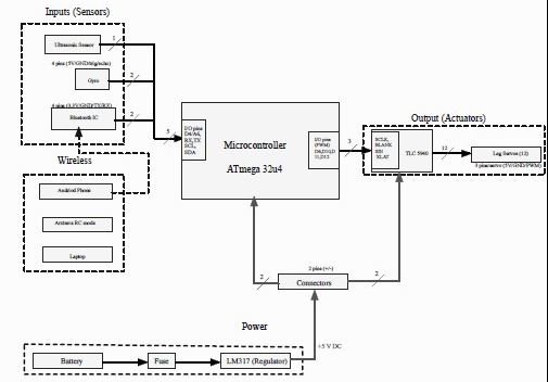
The block diagram for our micro biped project expresses how the components connected and set.
1- Inputs sensors:
Ultrasonic sensor (HC-SR04™) will send and receive pulses of sound to measure the distance to send to the microcontroller. The gyro will measure the orientation of the robot to keep the robot relatively stable. To connect to the Arxterra™ application a Bluetooth IC (HC-06™) will be connected to the microcontroller.
2- Wireless communications:
An Android phone will be used to communicate with the robot, and Axterra via Bluetooth. With capabilities through Community Mode, RC mode. They are not connected to the input physically, the dashed line represents a wireless signal. (HC06) bluetooth is connected between the Android phone and the Atmega32u4 microcontroller through Bluetooth.
3- Output:
There are 12 leg servo motors, 6 servos in the left leg and 6 servos in the right leg. These 12 servos are being controlled by connection with an Arduino microcontroller, Axterra operations control center, and Bluetooth through Android phone. From the larger BiPed design the group changed the location of the fuses and reduced their number because of two reasons.
- The fuses had to be changed from previous semesters because the microBiPed lacks the real estate to support 12 fuses.
- It is believed that if one fuse blows then the entire system would be faulty. Therefore instead of risking potential damage to the rest of the frame the group decided to have one fuse before the regulators to turn off.
The UBEC voltage regulator code also not be used because its size and weight, so to compensate the project used a LM3XX™ from Texas Instruments.
Brief Information on Arxterra:
Arxterra is a user interface that will read telemetry for customized robots and devices that is an essential part of the senior design course. The control panel allows for various tasks to be issued through a customizable panel for individual robots.
There are essentially three main options that can be selected: an on/off switch, list selection, and slide switches. The slide switches can be chosen with a desired range for speed which is assigned as either 8 bytes or 16 bytes. The list selection configuration will allow the user to select which mode their robot will be in, in this case there were three options: Run, Walk, and Crawl.
The fuses had to be changed from previous semesters because the microBiPed lacks the real estate to support 12 fuses.
The UBEC voltage regulator code also not be used because its size and weight, so to compensate the project used a LM3XX™ from Texas Instruments.

