By: Ameen Alattas
Since the project is using an Arduino Micro, there is not have enough PWM pins to control all of the servos. The microcontroller has 7 PWM pins but the project requires 12 servos, which means an additional 5 PWM pins are needed. Therefore, the group decided to use a TLC5940 since it has the ability to provide up to 16 PWM output pins.
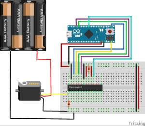
By connecting BLANK, XLAT, SCLK, and SIN to 4 pins on the Arduino Micro, DCPRG to power source, and VPRG to ground the chip gives the group 16 PWM output which is more then what is required.
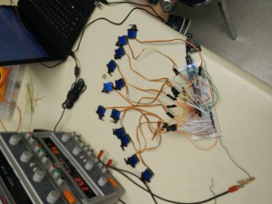
Additionally, ensure to connect the used outputs with pull up resistors that match the IREF resistor. The first time the group tried the TLC5940 to control servos without pull-up resistor no movement occurred. The TLC5940 could be found as a breakout boards or as a dip chip. Originally the group connected the TLC5940NT package in a similar fashion as the breakout board, however because the project is using a dip chip a different set up had to be used. In the video below the group has 12 servos hooked to the TLC5940 which is connected to the Arduino Micro. As one can see the TLC5940 allows for individual control of the servos.
For more information on the Arduino and the TLC5940 refer to the Arduino website at this link.
Below is a fritzing diagram of the TLC5940 connected to a Arduino Micros, The pin set-up is as follows:
Ardunio Micro : TLC5940
MOSI : SIN
SCK: SCLK
SS: No input, but has to be set
OC1A (D9) : XLAT
OC1B (D10) : for BLANK
OC3A (D5) : for GSCLK
To understand how the set-up was reached refer to this blog post.


