μDozer/Fall/2019
Authors: Moises Flores (Project Manager, Modeling), Deion Guillermo (Documentation), Jesus Rios (Mechanism)
Table of Contents
Introduction
Around the middle of the semester, the project status is presented in a Preliminary Design Review (PDR). This blog post documents the information presented at the time during PDR. The PDR was also one week right after our project mission was overhauled, so much of this information had been improved on in the weeks following PDR.
Project Objective
The main objective of the team is to build a robot based upon the Arxterra Goliath robots and take advantage of its small size to navigate underneath and behind furniture in order to recover and remove misplaced items and dust.
Mission Profile
The robot will be manually driven through remote controls that provide the option to use a live camera feed. Through these controls, the robot will have the ability to remove various small, light objects from underneath furniture and relocate the objects to an open area that an adult may easily pick up.
Standards and Constraints
The robot will be designed and built according to these constraints:
- All 3DoT robots shall incorporate the 3DoT v8 or later series of boards.
- Software shall be written in the Arduino De facto Standard scripting language and/or using the GCC C++ programming language, which is implements the ISO C++ standard (ISO/IEC 14882:1998) published in 1998, and the 2011 and 2014 revisions. Required exceptions to this standard can be found here.
- All 3DoT robots shall be in compliance with the 3DoT Command and Telemetry Packet specification.
- All 3DoT robots shall be controlled via Bluetooth 4.0 in compliance with the Bluetooth Special Interest Group (SIG) Standard (supersedes IEEE 802.15.1).
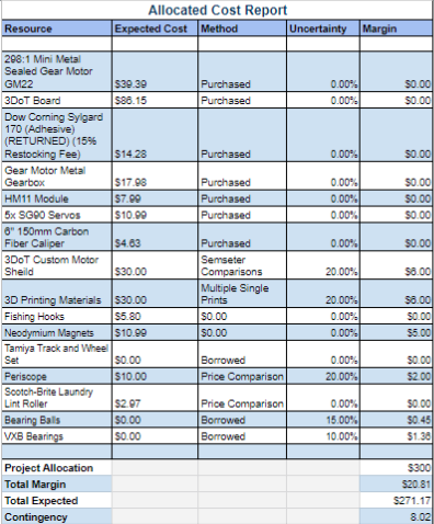
- MicroDozer shall not exceed a cost of $300.
As well as follow the following standards.
- IEEE 29148-2018 – ISO/IEC/IEEE Approved Draft International Standard – Systems and Software Engineering — Life Cycle Processes –Requirements Engineering.
- Bluetooth Special Interest Group (SIG) Standard (supersedes IEEE 802.15.1)
- C++ standard (ISO/IEC 14882:1998)
- Federal Communications Commission (FCC) Relevant standards for a product implementing a 2.4GHz radio, FCC Intentional Radiators (Radio) Part 15C, and Unintentional Radiators FCC Part 15B for CPU, memories etc.
- NXP Semiconductor, UM10204, I2C-bus specification and user manual.
- ATmega16U4/ATmega32U4, 8-bit Microcontroller with 16/32K bytes of ISP Flash and USB Controller datasheet section datasheet, Section 18, USART.
- USB 2.0 Specification released on April 27, 2000, usb_20_20180904.zip
- Motorola’s SPI Block Guide V03.06
Requirements
Level 1 Requirements
1.1: The robot shall push objects out from underneath and behind furniture.
1.2: The robot shall be able to traverse obstacles up to 7mm in height.
1.3: The robot’s locomotion shall be manually and remotely controlled.
1.4: The robot shall provide the option to display live camera feed from its front.
1.5: The robot shall have the option to illuminate its forward path with a lighting system.
1.6: The robot shall utilize a U-blade design to push objects.
1.7: The robot shall successfully collect dust off of carpeting, linoleum, and wooden floors.
1.8: The robot’s driving shall be accomplished through using no more than two drive motors.
Level 2 Requirements
2.1.1-a: The robot shall be built within the size of a 4in x 6in x 4in (10.16cm x 15.24cm x 10.16cm) rectangle.
This will be verified by measuring the bot’s dimensions using a 0.1mm accuracy digital caliper.
2.1.1-b: The non-metal parts and chassis shall be 3D printed using ABS in order to generate parts that function at its small size.
2.1.1-c: The robot shall be able to push a total load of 300 grams.
This will be verified measuring the total load with a digital scale with a minimum accuracy of 1 gram.
2.1.2-a: The robot shall lift its blade anywhere between 0° to 35° relative to its resting position using no more than one SG90 servo motor. This will allow the blade to undo any obstacle snagging.
This will be verified by measuring the angles with a protractor.
2.1.2-b: The robot shall use rubber treads to traverse over objects of 7mm in height.
2.1.3.a: The robot shall use the 3DoT V9 board and ArxRobot app custom commands to handle the manual controls. This will also serve the blade lifting (Requirement 1.2) and path illumination (Requirement 1.5).
This will be verified by confirming 360° turning and forward and reverse motion.
2.1.3.b: The robot shall use no more than two 1.2kg*cm torque Wal front motors to allow movement.
2.1.4: The robot shall use the ArxRobot Control Panel to control its movement while using the robot’s phone camera functionality.
2.1.5: The robot shall use a flashlight attachment with a value of 10 lumens.
This will be verified through the use of a light meter.
2.1.6: The robot’s blade shall be designed to have teeth with spacing of 5mm to be able to lift up objects while also taking objects with holes (such as key rings).
This will be verified by measuring the bot’s dimensions using a 0.1mm accuracy digital caliper.
2.1.7: The robot shall lift its blade anywhere between 0 to 35 relative to its resting position using no more than one SG90 servo motor. This will allow the blade to undo any obstacle snagging.
This will be verified by measuring the angles with a protractor.
2.1.8: The robot shall use a custom lint roller in order to pick up dust, lint, and short hairs.
This will be verified by checking if the roller is capable of picking up 80% of debris placed in its path. 80% is in reference to the amount of mass.
Design Innovation
Our robot has gone through 2 iterations before settling on our current model. Our original design did not have any previous relation to the projects found on ArxTerra. The inspiration for the original project was to replicate the functionality of Stanford’s μTugBots. These robots were small robots whose weight only totaled to about 12 grams and was constrained to a size of about 25 x 25 mm. Although small, this μTugBot is able to anchor down onto surface and pull a load of about 2000 times its own weight. This was accomplished using a very specific structure on the adhesive pad that the bot rests upon. The adhesive pad had a structure called “setae” which mimics the fibers found on animals such as geckos. When setae are in a neutral position, only the tips of the hairs make contact with the surface below. However, when a load is applied, it bends the setae – increasing its surface area in contact with the ground – and thus increases the adhesion. This mechanism for anchoring complements the size of the robot as it can provide strong adhesion within a small area. Further, the engagement of the adhesion only adheres in a single direction, meaning removing itself from a surface is simple enough such that the robot simply needs to lift its wheels.
When designing our own robot, we wished to replicate the functionality of the robot – anchoring and pulling – while upscaling the robot around the size of the 3Dot Board. Further, we originally designed for a four-wheeled robot rather than the two wheels of the μTugBot in order to avoid dragging the posterior of the bot along the ground. While working on the robot, many complications from these goals. For one, the setae’s structure incredibly difficult to manufacture without the proper tools. Each fibre of the setae is a size of 100 μm with an extremely tight margin of error of 1 μm. Unfortunately, the team decided to abandon the setae approach, as it may be too complex for the scope of this class.
First Iteration
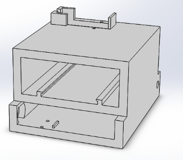
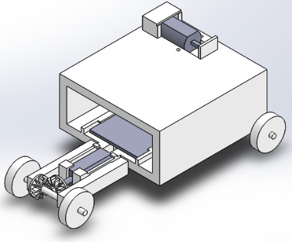
As we moved forward with the original design of the robot, we still have remnants of the robot’s original design. In the first iteration/ attempt at upscaling the robot, we modeled the bare minimum to accomplish the tasks that the robot required. This original chassis allocates the lowest layer of space for two servos that would each lift a set of wheels. The wheels would have been lifted in order for the base of the robot to make contact with the surface. The middle compartment is reserved for the 3DoT board, as well as grooves to keep the 3DoT from moving within the robot. Finally, the top portion is made to house a motor that acts as a winch for the robot.
Second Iteration
After the team decided to abandon the artificial setae approach, the mission and design also changed as well. Our mission changed to create a mobile winch rather than closely replicating Stanford’s work. In this change, this allowed the team to explore alternative ways for the robot to anchor down onto a surface. However, before we could move forward with a specific anchoring system, we performed a trade-off study to find the best system. The anchoring systems considered were magnets, sharkskin, microspines, suction cups, and rubber.
Trade Off Study
The anchoring mechanism trade-off study is found here: https://www.arxterra.com/?p=151050&preview=true
Even through these tests, a microspine array system would be ideal for the load it is able to withstand. However, through more discussion between the team as well as guidance from the professor, we determined the project’s goal as a whole did not have a practical real-world use. The utilizing the microspine array seemed unsuitable as a solution. Thus, another overhaul of the project was considered.
Current Design
After much needed discussion alongside the professor, the project received another major overhaul. First, the professor recommended following the long line of ArxTerra Goliath as basis for the mechanical side of the robot. This is because the Goliath constantly pushes for a more compact size with each iteration. Next, different brainstorming techniques were used to shift the goal from pulling an object to the exact opposite – pushing. With this, the project had a more realistic application for use, as well as simplifying the project as a whole – especially since the project time was running out. Going forward, the team decided to follow the design of E-racer, the previous robot with the smallest overall size.
System Block Diagram
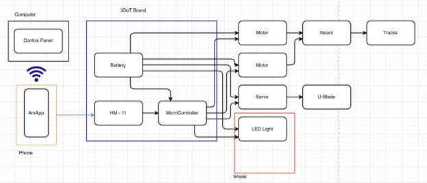
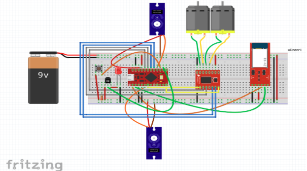
Pictured on the left is the main control interface a user would use: the ArxRobotApp as well as the external control panel using a personal computer. Through Bluetooth, the ArxRobotApp connects to the HM-11 Module attached to the 3DotBoard. From the board, it powers and controls the motors, servo, and the LED light for the robot.
Product Breakdown Schedule
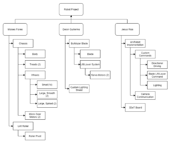
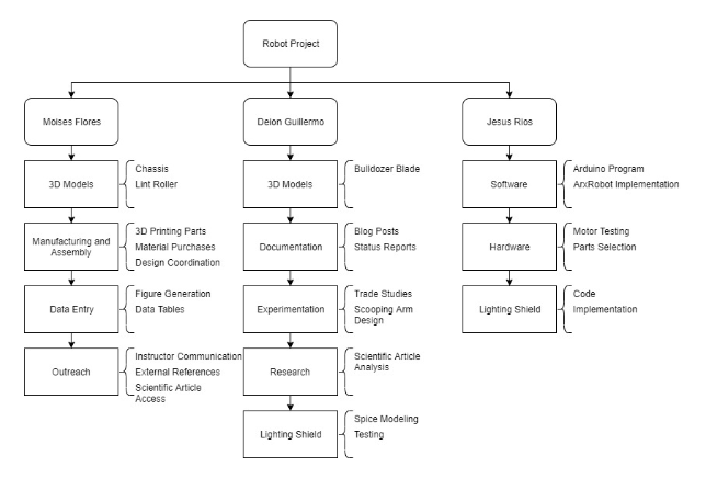
In the week between the project shift and PDR, the following project schedule was put together. The entire project was broken down into the tasks that needed to be done for this new robot and then the tasks were split among the team according to the strengths of each member. Moises would be responsible for a bulk of the modelling: adjusting the chassis of the robot to accomodate for the extra attachments as well as modeling the lint roller for the robot. Deion will assist and cooperate with Moises with modelling, as he will be constructing the bulldozer blade. This part of the robot is rather integral for the robot, and will affect the Moises’s modifications to the chassis. Afterwards, Deion will turn to work alongside Jesus and design the custom PCB shield for the lighting system. Jesse will be working with the software of the robot, especially the commands related to the ArxRobotApp. The functionality with the app includes driving the bot, lifting the dozer blade, and turning on the flashlight. He will also closely work with the 3Dot Board in order to communicate with the application.
Software – ArxRobot App
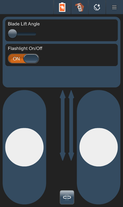
At the moment, we have a very simple interface for the user. As we assume this robot can be operated by anyone age 6+, a simple interface is desired. The first option for the robot is the blade life angle slider. This slider ranges from values between 0 to 35, each value related to an angle for the dozer blade in relation to the surface. The next option is the flashlight on off switch; it’s pretty self explanatory. The last option for on the app is the tank sliders that control the respective left and right tracks of the robot.
Software – 3DoT Firmware
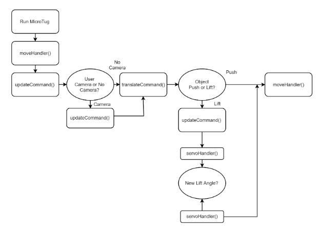
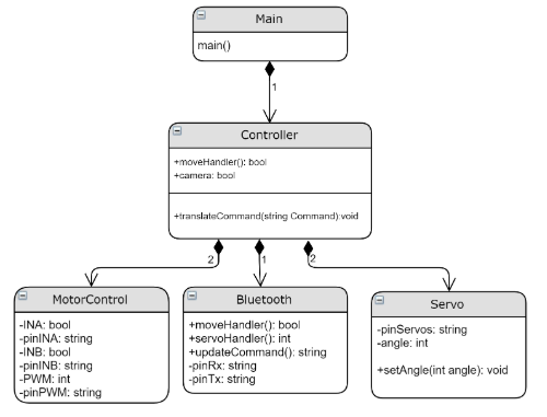
The diagram above shows the current software block diagram. As the commands flow through, there is a block involving the camera. We imagine the user to have the option to use the camera, not forced to use the camera. Once the robot confirms whether or not the user is using the camera, it then moves on to see if the robot needs to push the object or lift. If push, the robot simply needs to drive forward. If lift, the commands flow through to find the new angle the blade need to set at.
Function and Variable Descriptions
Electronic Systems Design
Mechanical Design
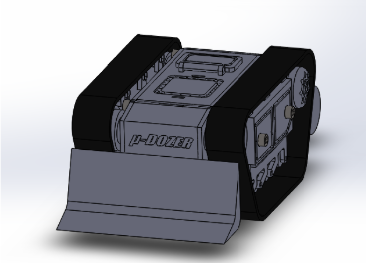
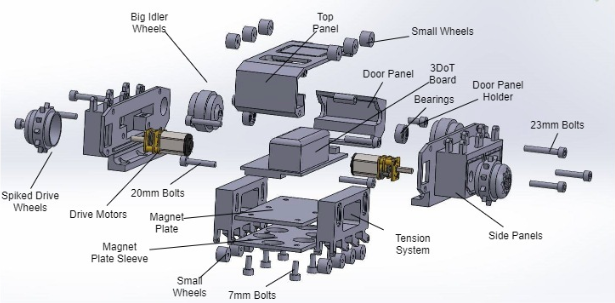
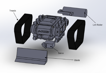
A significant portion of the design will be based off of the previous generation’s E-Racer. As stated before, Goliath has progressively optimized the space allocation to make the robot smaller and smaller; E-racer is the most compact of the six completed generations. Compared to E-racer, μDozer will have many attachments added onto it. These include one internal addition – an SG-90 Servo – as well as two external additions – the Dozer Blade and the Lint Roller. To accommodate for these new additions, the main body will likely be expanded length-wise.
For a quick visualization, a mock-up for the dozer blade as well as the lint roller have been put together.
Mechanical Design – Motors
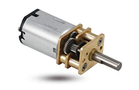
For the motors that will drive the tracks, we will be utilizing the Micro Metal Gear Motors. Each motor will be positioned to turn a spiked drive wheel near the posterior of the bot. These spiked drive wheels insert between the tracks to grant the robot its locomotion. Referencing the previous generation, they used the Pololu 290:1 metal gear motor design. This was fortunate for us, as we already had 298:1 metal gear motors in our possession. We originally had these motors as test motors for the winch of the previous mission. Now we have repurposed them to be used as drive motors for the robot.
Mechanical Design – Servos
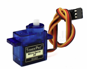
The dozer blade will be lifted by a SG-90 Servo. We chose to have the dozer blade lift up slightly to a maximum angle of 35 degrees. Some applications for this lifting can be to traverse over an obstacle such as a wire along the floor, or to push the objects within the blade deeper into the blade. The SG-90 is also applicable for lifting the dozer blade as the dozer blade will be constructed to be relatively lightweight. Other considerations were the cheap price to acquire these servos, as well as the fact that we also had these for the previous mission as well. The original use was to lift the wheels of the robot such that the base of the robot can make contact with the floor. Now these can be repurposed like the motors, since we already had these in our possession.
Mechanical Design – Bearings
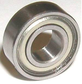
The tracks of the robot are driven by the motors seen previously. As a pair to these motors and the spiked drive wheels, there will be two idler wheels to maintain the shape and tension of the tracks. These idler wheels will be coupled with 623ZZ Miniature Shielded Bearings to decrease the friction in these idler wheels. For specific measurements, the inner diameter is 3mm, the outer diameter is 10mm, and the width measures to 4mm.
Mechanical Design – U-Blade
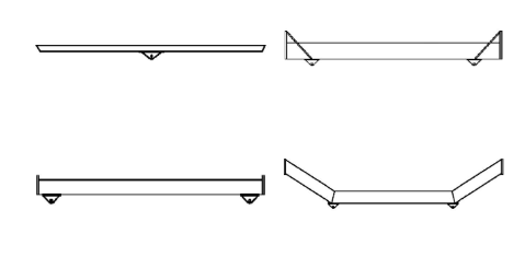
In the small time between changing the mission and the next deadline for the Preliminary Design Report, the main goal we now needed to accomplish is to push. The first idea that comes to mind thats associated with the word push would be a bulldozer. Quickly we set out to research which blade design for bulldozers would benefit our goal. There are different designs for each dozer blade that each serve different purposes.
Comparing four different dozer designs: angle dozer, straight dozer, U-blade, and semi U-blade. The angle dozer has one point of union that can pivot left or right, allowing the bulldozer to move material left and right. The straight dozer is a flat blade that is great for its strength, but has a weakness of having material spill out the sides. A U-blade is specifically designed for pushing large quantities of material over long distances. Lastly, the semi U-blade combines aspects of the straight dozer and the U-blade; it has the strength similar to the straight blade, and has wings to prevent material spilling similar to the U-blade. For our robot, we decided to follow a U-blade design for pushing the small objects.
Mechanical Design – Dust Roller
The dust roller will be modeled after typical household lint roller, with some adjustments to suit the robot. The dust roller will be attached to the chassis of μDozer similar to the structure of a paint roller. At the base of this connection will be a bearing ball to unite the chassis and the dust roller. This bearing ball will allow more freedom of movement for the dust roller as it follows the μDozer. Further, a bearing ball union can potentially prevent the dust roller from getting caught on obstacles as it drives. Lastly, the ball bearing will allow the user to attach and remove the dust roller easily.
Work Breakdown Structure
Design & Unique Task Descriptions
Deion Guillermo:
- Dozer Blade and Lifting Arm
- Research structure and teeth spacing (1 week)
- Submit first iteration design to print and test for CDR (1 week)
- Will have to coordinate design with chassis model
- Adjust and finalize design (2 weeks)
- Lighting Shield
- Design PCB for lighting shield and submit for building (2 weeks)
- Will have to coordinate with coding
- Troubleshoot PCB to ensure functionality, will be used in final design (1 weeks)
- Design PCB for lighting shield and submit for building (2 weeks)
Jesus Rios:
- Coding
- Generate code for drive motors and lifting servos (2 weeks)
- Generate code for illumination levels (1 week)
- User will be able to control brightness
- Research and implement integration of phone camera with ArxRobot control panel (1 week)
- App
- Develop custom commands for driving and blade lifting for CDR (1 week)
- Develop custom commands for light levels (1 week)
- Research and implement use of phone camera with ArxRobot control panel (1 week)
- Final debugging of code for final presentation (1 week)
Moises Flores:
- Lint roller design
- Research structure and adhesion (1 week)
- Build first iteration design and test (1 week)
- Must be coordinated with chassis
- Adjust and finalize design (2 weeks)
- Chassis
- Finalize location of servos and motors (1 week)
- This will help minimize length of robot
- Coordinate with team on how to attach dozer blade for CDR and print (2 weeks)
- Coordinate with team on how to attach lint roller; confirm functionality of periscope (1 week)
- Finalize print for testing and submission (1 week)
- Finalize location of servos and motors (1 week)
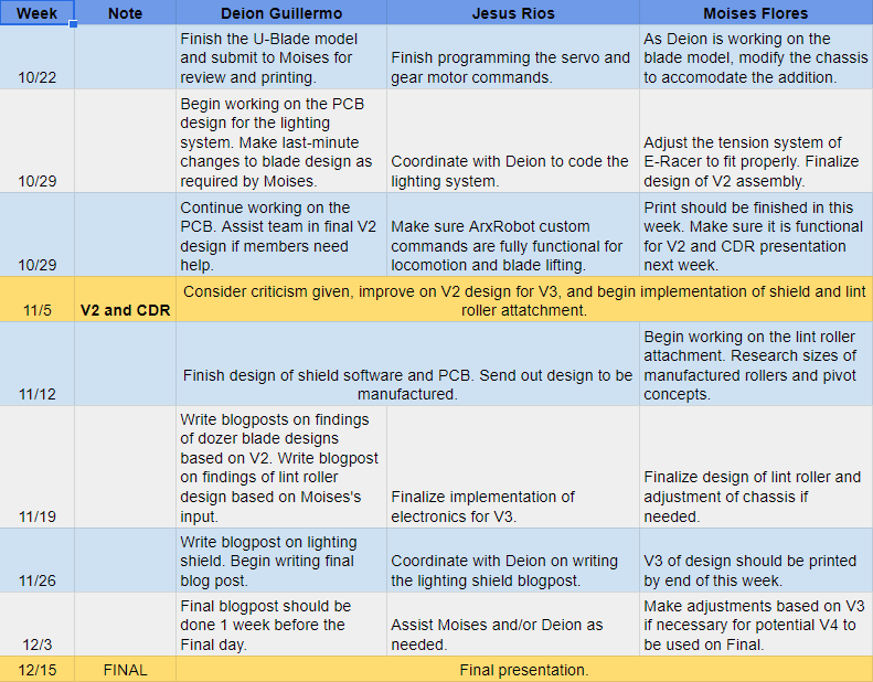
Project Schedule
Project Schedule – Waterfall Diagram
The critical path of the project for the remainder of the semester is highlighted in red. In the two weeks before V2, we plan to have the robot able to be driven around as well as lift it’s blade. The other features will be started but are not the highest priority for the V2 demo. However, if everything goes well these features may be ready for V2. After V2 and CDR, the additional features such as the dust roller and the camera compatibility will be given full attention.

