Interrupts and 16-bit Timer/Counter 1: Atmel AVR Timers and Interrupts
Reading
The AVR Microcontroller and Embedded Systems using Assembly and C
by Muhammad Ali Mazidi, Sarmad Naimi, and Sepehr Naimi
Section: 10.2
Table of Contents
Interrupt Basics – Review –
ATmega328P Interrupt Vector Table
| Vector No | Program Address | Source | Interrupt Definition | Arduino/C++ ISR() Macro Vector Name |
|---|---|---|---|---|
| 1 | 0x0000 | RESET | Reset | |
| 2 | 0x0002 | INT0 | External Interrupt Request 0 (pin D2) | (INT0_vect) |
| 3 | 0x0004 | INT1 | External Interrupt Request 1 (pin D3) | (INT1_vect) |
| 4 | 0x0006 | PCINT0 | Pin Change Interrupt Request 0 (pins D8 to D13) | (PCINT0_vect) |
| 5 | 0x0008 | PCINT1 | Pin Change Interrupt Request 1 (pins A0 to A5) | (PCINT1_vect) |
| 6 | 0x000A | PCINT2 | Pin Change Interrupt Request 2 (pins D0 to D7) | (PCINT2_vect) |
| 7 | 0x000C | WDT | Watchdog Time-out Interrupt | (WDT_vect) |
| 8 | 0x000E | TIMER2 COMPA | Timer/Counter2 Compare Match A | (TIMER2_COMPA_vect) |
| 9 | 0x0010 | TIMER2 COMPB | Timer/Counter2 Compare Match B | (TIMER2_COMPB_vect) |
| 10 | 0x0012 | TIMER2 OVF | Timer/Counter2 Overflow | (TIMER2_OVF_vect) |
| 11 | 0x0014 | TIMER1 CAPT | Timer/Counter1 Capture Event | (TIMER1_CAPT_vect) |
| 12 | 0x0016 | TIMER1 COMPA | Timer/Counter1 Compare Match A | (TIMER1_COMPA_vect) |
| 13 | 0x0018 | TIMER1 COMPB | Timer/Counter1 Compare Match B | (TIMER1_COMPB_vect) |
| 14 | 0x001A | TIMER1 OVF | Timer/Counter1 Overflow | (TIMER1_OVF_vect) |
| 15 | 0x001C | TIMER0 COMPA | Timer/Counter0 Compare Match A | (TIMER0_COMPA_vect) |
| 16 | 0x001E | TIMER0 COMPB | Timer/Counter0 Compare Match B | (TIMER0_COMPB_vect) |
| 17 | 0x0020 | TIMER0 OVF | Timer/Counter0 Overflow | (TIMER0_OVF_vect) |
| 18 | 0x0022 | SPI, STC | SPI Serial Transfer Complete | (SPI_STC_vect) |
| 19 | 0x0024 | USART, RX | USART, Rx Complete | (USART_RX_vect) |
| 20 | 0x0026 | USART, UDRE | USART, Data Register Empty | (USART_UDRE_vect) |
| 21 | 0x0028 | USART, TX | USART, Tx Complete | (USART_TX_vect) |
| 22 | 0x002A | ADC | ADC Conversion Complete | (ADC_vect) |
| 23 | 0x002C | EE READY | EEPROM Ready | (EE_READY_vect) |
| 24 | 0x002E | ANALOG COMP | Analog Comparator | (ANALOG_COMP_vect) |
| 25 | 0x0030 | TWI | 2-wire Serial Interface | (I2C) (TWI_vect) |
| 26 | 0x0032 | SPM READY | Store Program Memory Ready | (SPM_READY_vect) |
ATmega328P Enabling an Interrupt – Timer/Counter 1
- All interrupts are assigned individual enable bits which must be written logic one together with the Global Interrupt Enable bit in the Status Register (SREG) in order to enable the interrupt.
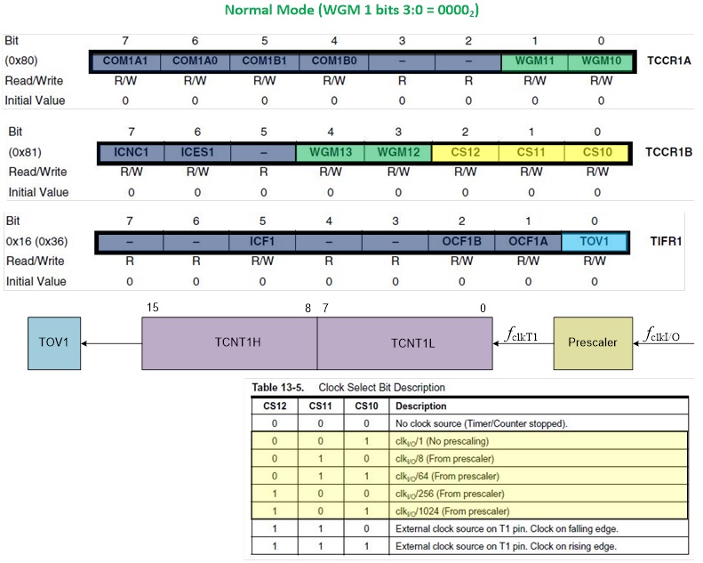
- For example, to allow the Timer/Counter 1 Overflow flag (TOV1) to generate an interrupt you would set the Timer/Counter 1 Overflow Interrupt Enable (TOIE1) bit.
- When Timer/Counter 1 Overflows (0xFFFF
0x0000) the TOV1 bit is set to 1.
- With global interrupt I-bit set and Timer/Counter 1’s Overflow Interrupt Enable TOIE1-bit set, when the Overflow TOV1-bit is set an interrupt will be generated and the Program Counter (PC) will be vectored to Flash Program Memory address 0x001A (see IVT Table on previous page). The AVR processor starts running the ISR.
- The TOV1 flag is automatically cleared at the beginning of the interrupt service routine. Alternatively, if you are polling the flag, it can be cleared by writing a logical one to it. The TIFR1 register is within the I/O address range (0x00 to 0x1F) of the Set Bit in I/O Register (SBI) Instruction.
Timer/Counter 1 Normal Mode – Design Example
See Lecture 9 for the design example.
ATmega328P Enabling Timer/Counter 1 Interrupt
// Jump over and Setup the Interrupt Vector Table
RST_VECT:
rjmp reset
// TIMER1 OVF vector = 0x001A, Sect 9.4 Interrupt Vectors in ATmega328P
.ORG OVF1addr
jmp TOVF1_ISR // Section 4.7 Reset and Interrupt Handling
; Set prescale and start Timer/Counter1
ldi r16,(1<<cs11)|(1<<cs10) //prescale of 64 sect 15.11.2
sts TCCR1B,r16 // Table 15-5 Clock Select Bit Description
ldi r16,0x0B // load value high byte (Sect 15.2-15.3)
sts TCNT1H,r16
ldi r16,0xDC // load value low byte
sts TCNT1L,r16
// Enable Local and Global Interrupts
ldi r16,(1<<toie1) //enable interrupts for timer1 OVF
sts TIMSK1,r16 // TIMSK1 Bit 0 – TOIE1
sei // Global Interrupt Enable
The Interrupt Service Routine (ISR)
; — Timer/Counter 1 Overflow Interrupt Service Routine —
; Called on Timer/Counter1 overflow TOV1
; TOV1 flag automatically cleared by AVR on interrupt
TOVF1_ISR:
push reg_F
in reg_F,SREG
push r16
; — 250 msec —
ldi r16,0x0B // load value high byte 0x0B
sts TCNT1H,r16
ldi r16,0xDC // load value low byte 0xDC
sts TCNT1L,r16
; — Blink Discrete LED —
ldi r16,0b10000000 // toggle LED
eor spiLEDS, r16
pop r16
out SREG,reg_F
pop reg_F
reti
; ——————————————————-


