Spring 2016: 3DoT David Arxterra Firmware Configuration
By: Chris Hirunthanakorn (Systems, Mission, and Test)
Table of Contents
Arxterra Firmware Configuration for 3DoT David
Introduction:
Because the 3DoT David is going to be controlled by the Arxterra App, the robot must use the Arxrobot Firmware that is available from here (https://github.com/arxterra/arxrobot-firmware/releases). For our particular robot, there were several things that needed to be changed or added such as the code for the tagging system, the subroutines for controlling the motors, and any custom commands that need to be added. This blog post covers all of the work done for the configuration of the Arxrobot Firmware for the 3DoT David as it went through various design changes and revisions.
Related Requirement:
All of the information presented in this blog post is related to the following project level requirement.
- The 3DoT David shall be controlled by the Arxterra App used on a smartphone.
First Modification of Arxrobot Firmware for PDR Demonstration
Because the 3DoT board was not ready for use by the PDR Demonstration, the base of a store bought hexbug was used with an Arduino Uno and an Adafruit Motor Shield in order to demonstrate the control of the robot with the Arxterra App. The first modification to the Arxrobot Firmware included changes to the pin and command definitions in the pinouts_robot.h file, including the header files needed for the Adafruit Motor Shield, and the creation of functions needed to control the motors and the movement of the robot.
Changes to the pinouts_robot.h file
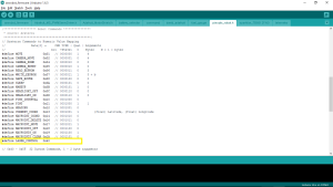
There was only one change to the pinouts_robot.h file, which was the addition of one custom command definition. This is the LASER_CONTROL command that is meant to demonstrate the control of our tagging system.
Changes to the command handler function
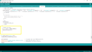
The first change to the command handler function involves changing which function is called when the move command is sent from the Arxterra App. Instead of calling the move_TB6612FNG() function, it now calls our detectDir() function.
The second change is to add the new custom command for LASER_CONTROL. A new elif block is added to execute the correct function when the custom command is sent. Functions to control motors and movement of the robot
Our Electronics and Control Engineer helped me create these functions by showing how to control the motors using the Adafruit Motor Shield. The detectDir() function interprets the move command sent from the Arxterra App to determine the direction the user wants the robot to move. From there, it will call the corresponding function that will move the motors. For example, if the direction is forward, the move_camf() function will be called and that function will cause the camMotor to start. The laser_status() function is for demonstrating the use of a custom command to control our laser/tagging system by turning an LED on or off.
void adafruitinit(){
pinMode(10, OUTPUT); // Sets pin A10 as an output
}
void detectDir(uint8_t * motordata){
// Create the motor shield object with the default I2C address
Adafruit_MotorShield AFMS = Adafruit_MotorShield();
Adafruit_DCMotor *headMotor = AFMS.getMotor(1);
Adafruit_DCMotor *camMotor = AFMS.getMotor(2);
AFMS.begin(); // create with the default frequency 1.6KHz
uint8_t headdir = motordata[3];
uint8_t camdir = motordata[5];
if (headdir == 1 && camdir == 1){ // forward
move_camf(camMotor, motordata[6]);
}
if (headdir == 1 && camdir == 2){ // right
move_headr(headMotor, motordata[4]);
}
if (headdir == 2 && camdir == 1){ // left
move_headl(headMotor, motordata[4]);
}
if (headdir== 2 && camdir == 2){ // backwards
move_camb(camMotor, motordata[6]);
}
if (headdir == 3 && camdir == 3){ // Brake
motor_brake();
}
if (headdir == 4 && camdir == 4){ // Release
headMotor -> run(RELEASE);
camMotor -> run(RELEASE);
}
}
void motor_brake(){
}
void move_camf(Adafruit_DCMotor *camMotor, byte pwm){
camMotor -> setSpeed(pwm);
camMotor -> run(FORWARD);
}
void move_camb(Adafruit_DCMotor *camMotor, byte pwm){
camMotor -> setSpeed(pwm);
camMotor -> run(BACKWARD);
}
void move_headr(Adafruit_DCMotor *headMotor, byte pwm){
headMotor -> setSpeed(pwm);
headMotor -> run(FORWARD);
}
void move_headl(Adafruit_DCMotor *headMotor, byte pwm){
headMotor -> setSpeed(pwm);
headMotor -> run(BACKWARD);
}
void laserStatus(byte stat){
if (stat == 1){
digitalWrite(10, HIGH);
}
if (stat == 0){
digitalWrite(10, LOW);
}
}
Second Modification of Arxrobot Firmware
After the PDR Demonstrations, we were able to obtain the Sparkfun TB6612FNG Dual Motor Driver that is used on the 3DoT board and made the modifications to the Arxrobot Firmware to use this hardware instead. The changes made include removing the header files for the Adafruit Motor Shield, changing the functions used to control the motors, and modifying the functions in the sparkfun_TB6612FNG file. There were also a few additional definitions that were added to the pinouts_robot.h file.
Additions to the pinouts_robot.h file
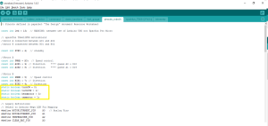
Definitions for which motor and which direction were added to the pinouts_robot.h file.
Changes to functions to control motors
The main changes to the detectDir() function are that they use the modified functions from the sparkfun_TB6612FNG file.
void detectDir(uint8_t * motordata){
uint8_t headdir = motordata[3];
uint8_t camdir = motordata[5];
if (headdir == 1 && camdir == 1){ // forward button pressed – move cams motor forward
move_TB6612FNG(cammotor, turnCW, motordata[6]);
}
if (headdir == 1 && camdir == 2){ // right button pressed – move head motor right
move_TB6612FNG(headmotor, turnCCW, motordata[4]);
}
if (headdir == 2 && camdir == 1){ // left button pressed – move head motor left
move_TB6612FNG(headmotor, turnCW, motordata[4]);
}
if (headdir== 2 && camdir == 2){ // backwards button pressed – move cams motor backwards
move_TB6612FNG(cammotor, turnCCW, motordata[6]);
}
if (headdir == 3 && camdir == 3){ // Brake
brake_TB6612FNG(headmotor);
brake_TB6612FNG(cammotor);
}
if (headdir == 4 && camdir == 4){ // Release
release_TB6612FNG(headmotor);
release_TB6612FNG(cammotor);
}
}
Here is the updated code for the sparkfun_TB6612FNG file.
void setup_TB6612FNG(){
pinMode(STBY, OUTPUT);
pinMode(PWMA, OUTPUT); // motor A
pinMode(AIN1, OUTPUT);
pinMode(AIN2, OUTPUT);
pinMode(PWMB, OUTPUT); // motor B
pinMode(BIN1, OUTPUT);
pinMode(BIN2, OUTPUT);
brake_TB6612FNG(0); // brake
brake_TB6612FNG(1);
}
void brake_TB6612FNG(boolean motorNumber) // initialize or stop TB6612FNG
{
/* This stops the specified motor by setting both IN pins to HIGH */
if (motorNumber == headmotor) {
digitalWrite(AIN1, HIGH);
digitalWrite(AIN2, HIGH);
}
else
{
digitalWrite(BIN1, HIGH);
digitalWrite(BIN2, HIGH);
}
digitalWrite(STBY, HIGH);
}
void safeRover()
{
digitalWrite(STBY, HIGH); // TB6612FNG disabled (high impedance)
}
void move_TB6612FNG(boolean motorNumber, boolean motorDirection, int motorSpeed)
{
/* This Drives a specified motor, in a specific direction, at a specified speed:
– motorNumber: motor1 or motor2 —> Motor 1 or Motor 2
– motorDirection: turnCW or turnCCW —> clockwise or counter-clockwise
– motorSpeed: 0 to 255 —> 0 = stop / 255 = fast */
boolean pinIn1; //Relates to AIN1 or BIN1 (depending on the motor number specified)
//Specify the Direction to turn the motor
//Clockwise: AIN1/BIN1 = HIGH and AIN2/BIN2 = LOW
//Counter-Clockwise: AIN1/BIN1 = LOW and AIN2/BIN2 = HIGH
if (motorDirection == turnCW)
pinIn1 = HIGH;
else
pinIn1 = LOW;
//Select the motor to turn, and set the direction and the speed
if(motorNumber == headmotor)
{
digitalWrite(AIN1, pinIn1);
digitalWrite(AIN2, !pinIn1); //This is the opposite of the AIN1
analogWrite(PWMA, motorSpeed);
}
else
{
digitalWrite(BIN1, pinIn1);
digitalWrite(BIN2, !pinIn1); //This is the opposite of the BIN1
analogWrite(PWMB, motorSpeed);
}
//Finally , make sure STBY is disabled – pull it HIGH
digitalWrite(STBY, HIGH);
}
void release_TB6612FNG(boolean motorNumber){
if (motorNumber == headmotor) {
digitalWrite(AIN1, LOW);
digitalWrite(AIN2, LOW);
}
else
{
digitalWrite(BIN1, LOW);
digitalWrite(BIN2, LOW);
}
digitalWrite(STBY, HIGH);
}
Final Modifications
Due to several changes with the design of the 3DoT David, there were modifications to the functions that control the motors and the tagging system. With the new movement system design, both motors will need to be controlled at the same time in order to move because each motor is driving one set of three legs. Additionally, the smoothest movement of the legs required the PWM value to be set to the maximum of 255. If it was any less, the motion of the 3DoT David would look very slow and feel weird. Because of the way the ArxRobot App is set up, the user has to press and hold the direction button to increase the speed of the motors to move in that direction. The code was changed so that the PWM value would be a constant 255 and that the leg movements would be fluid.
For the emitter part of the tagging system, it was decided that the IR emitter will be on whenever the 3DoT David is moving and is off the rest of the time. This is because the ArxRobot App can only send one command at a time and the alternative method of controlling the IR emitter would be using a slider on the app to turn it on or off. Implementing this in the code was easily done by incorporating the command into section of the commandHandler function that executed the move commands.
For the detector part of the tagging system, code was added to the main loop to check the output of the IR detector and if the 3DoT David should be disabled. The code is executed after the commandHandler function is called and checks if the robot has been tagged. If so, a counter would be incremented and if that counter reaches three, the robot will be disabled. When hit, the speaker will make a sound and the robot will not check for tags for 5 seconds. When the robot is disabled, it will not respond to any commands for 10 seconds and play a short song to indicate this change. All of this is done by using a flag variable to keep track of whether or not a tag has occurred. The flag will be cleared after 5 seconds have passed. When this has happened three times, the code will enter a loop that keeps it from responding to commands for 10 seconds.
Additionally, all of the extraneous code that was a part of the latest version of the arxterra firmware was removed. This includes all of the telemetry and sensor definitions that were left over from older projects that are not being used for the 3DoT David. All of the code used for debugging and testing were also removed or commented out to make sure additional processing time was not being used up.
Conclusion:
This blog post explains the process of the development of the Arxterra firmware code. It covers all of the changes done to prepare the demonstrations for the PDR and CDR.
Sources:
