Spring 2016: 3DoT David IR Emitter/Detector Testing
BY: Kent Hayes (Electronics and Control)
Introduction:
In order to implement a “laser tagging” system, the electronics and control engineer conducted research and performed tests in order to see that it is possible. You can view the results of the IR Trade off Study in our blog post (insert link to blog here). Taking these results he built the circuit shown in the PCB design blog post (insert link to PCB design process blog) to test the IR emitter and receiver.
Requirements:
- As a part of the subsystem requirements, this test is to determine if we can achieve the 5ft (2m) of range with the IR emitter/receiver system.
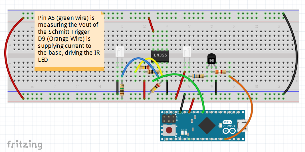
(Fig. 1: Fritzing Diagram of IR System)

While doing tests for sensitivity, he noticed the more you decreased the resistance being fed into the collector of the BJT, the more effective the IR emitter would become. In addition, the more you increase the resistance connecting from VCC to the detector, the more sensitive the detector would become. The detector was not receiving an IR signal further than 1ft from the emitter. As the components moved closer towards one another, the output voltage of the detector would decrease
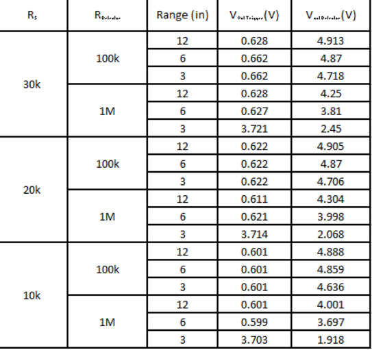
Table of results from varying resistors and ranges
Conclusion:
The best results appear to come when the RDetector is increased and not when R5 is changed. Even then, when we have such a short range which is only 3in. After reading a bit more online, Kent found the only other thing there is to increase the range of the IR emitter is a focusing lens made for LEDs. Depending on how wide the angle of the emitter is, how long the focal length is, and how wide the diameter of the lens is, we can then design our own lens tube. The following image is a table of how one might go about designing their own lens tube with various values:

We have ordered lenses and will begin testing to determine the most efficient design in order to meet the 5ft maximum range requirement.
Resources:
Lense Tube Table | http://www.lasertagparts.com/mtoptics.htm