3DoT Biped barbEE Generation #6/Spring/2019
Blog Post
Author/s:
Cynthia Lopez (Project Manager)
Hector Aguilar (E&C)
Donovan Minto (MST)
Connor Hearn (D&M)
Table of Contents
Executive Summary
By: Cynthia Lopez
Program and Project Objectives
Program Objective
The Robot Company (TRC) will be debuting its 2019 line-up of toy robots and associated games at the Toy-Invasion 2019 convention. Your team’s assignment is to make the 3D printed and/or laser-cut prototypes to be showcased at the convention, prior to production starting in the second quarter of 2019. The robots will feature our new ArxRobot smart phone application and the Arxterra internet applications allowing children to interact and play games around the world. In addition, the robots should be able operate autonomously in game mode. See game(s) (i.e, mission objectives) assigned to your robot by the Game Division. To decrease electronics cost, interoperability between all TRC robots will be maintained by incorporation of the 3DoT board, developed by our Electronics R&D Section. Modification of downloadable content is limited to software switch setting and robot unique graphics of the smart phone and Arxterra applications. Modifications of electronics is limited to custom 3DoT shields as required by the unique project objectives of your robot. The Marketing Division has set our target demographic as children between the ages of 7 and 13, with a median (target) age of 11. To decrease production costs, please keep robots as small as possible, consistent with our other objectives. As with all our products, all safety, environmental, and other applicable standards shall be met. Remember, all children, including the disabled are our most important stakeholders. Our Manufacturing Division has also asked me to remind you that Manufacturability and Repairability best practices must be followed.
Project Objective
The Biped team was assigned to go based of the Three Compliant Leg Modules Kinematic Design of Six-bar Linkages Robotics and Automation Laboratory by University of California, Irvine created by Mark Plecnik, Veronica Swanson and J. Michael McCarthy. To implement a toy robot that is capable of walking in two legs utilizing a 3DoT Board. The robot will use two D.C. motors as the main driver for the walking motion. Project Biped was able to demonstrate the walking mechanism with this jointless leg.
Mission Profile
Spring 2019 Biped was inspired by the previous generation of the Biped Theo Jansen. The Theo Jansen mechanism led use to find a similar alternative. The six linkage mechanism from UCI used to be transformed for the usage for a two legged in ordered to be a biped robot. Biped should be able to complete the Mission Objectives that are stated in the document.
Project Features
Theo Jansen Leg
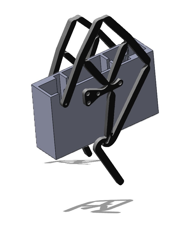
The method was inspired by the Dutch artist Theo jansen. He produced robots that were powered by wind as it walks. This method was inspired to pursue Mark Plecnik’s Six-Bar Linkage
Six-Bar Path Generating Linkage
Plecnik’s kinematic design takes a different approach for the path generation. “The design of the path generators is formulated as RR chains constrained to have a single degree-of freedom by attaching six-bar function generators to them.”
The Design
1.) No separate parts since it only has hinges or/ ligaments by laser cutting polypropylene for this design.
2.) The material used is rigid yet flexible. Allowing the leg to be able to withstand the weight of the body and capability to walk with the hinges.
Requirements
Engineering Standards and Constraints
Review and show compliance with constraints on the project imposed by The Robot Company (i.e., CSULB) and Project Stakeholders. Specifically include University and applicable environmental, health, and safety standards and those safety standards specifically associated with the product (e.g., Children’s Toys).
Applicable Engineering Standards
1.) IEEE 29148-2018 – ISO/IEC/IEEE Approved Draft International Standard – Systems and Software Engineering — Life Cycle Processes –Requirements Engineering.
2.) NASA/SP-2007-6105 Rev1 – Systems Engineering Handbook
3.) Bluetooth Special Interest Group (SIG) Standard (supersedes IEEE 802.15.1)
4.) C++ standard (ISO/IEC 14882:1998)
Environmental, Health, and Safety (EH&S) Standards
1.) CSULB College of Engineering (COE) Safety Resources. Start your search for applicable CSULB COE Safety Standards and Procedures here. Please review and acknowledge if any safety issues as defined by the COE applicable to your project.
2.) CSULB COE Lab Safety
3.) CSULB Environmental Health & Safety (EH&S)
4.) IEEE National Electrical Safety Code (NESC)
5.) NCEES Fundamental Handbook (FE) Reference Handbook
6.) ASTM F963-17, The Standard Consumer Safety Specification for Toy Safety, is a comprehensive standard addressing numerous hazards that have been identified with toys. In 2008, the Consumer Product Safety Improvement Act of 2008 (CPSIA) mandated that the voluntary toy safety standard in effect at that time become a nationwide mandatory children’s product safety rule.
7.) NFPA 70E Standard for Electrical Safety Requirements for Employee Workspaces
Disposal Of Hazardous Waste including Electronic and Solar Cells
CSULB Physical Planning and Facilities Management (PPFM) Environmental Compliance Electronic Waste Handling and Disposal Procedures. This lays out the procedures and policies regarding hazardous waste and E-waste. We shall follow these guidelines for the proper disposal of batteries, or any other electronics that can cause harm to health or the environment.
Program Level 1 Requirements
Project/Economic
Subcategories: Cost, Extensibility, Interoperability, Maintainability, Quality, Marketability, and Schedule
All 3DoT robots shall be constrained to a not to be exceed Cost of $250.
All project Schedules shall be constrained to a completion date of Monday May 13, 2019. Project completion includes documentation and materials purchased by or loaned to the project.
One of the Economic Factors affecting our robots are return rates. To demonstrate the durability and child friendliness of our robot a simple drop test from 1.4 meter should be performed. The height is defined by the average height of an average 11 year old girl.
Extensibility is designed into the 3DoT board by way of one 8-pin 100 mil connector located on the front of the board and two 8-pin 100 mil connectors located on the top of the board. By plugging shields into these connectors, the 3DoT board can support a diverse set of robots. All robots shall contain one or more custom designed 3DoT shields. The 3DoT shield(s) incorporating interface electronics between the 3DoT board and sensors and/or actuators unique to the robot. Surface Mount Technology (SMT) will be employed unless a waiver for through-hole parts is granted.
Maintainability: Disassemble and Reassemble of the robot shall be constrained to less than 20 minutes (10 + 10 minutes). Disassembly: The 3Dot board is clear of all other electronic and mechanical subassemblies. All electronic and mechanical subassemblies and associated connectors, sensors, and actuators including motors are disconnected. A functional test of the robot is conducted after reassembly to confirm its functionality. All project may reference a cable tree as well as an assembly diagram as necessary. This requirement is demonstrated/verified on the last day of the schedule. Projects may request a waiver with justification.
Social and Ethical
Subcategories: Accessibility, Aesthetics, and Usability
Accessibility by the blind and Marketability of the robots shall be implemented/enhanced by a speaker. The speaker shall generate sound effect consistent with the type of the robot. For example, the Goliath tank would make “track” sounds, the AT-ST sound effects would mimic their Star Wars antecedent.
Wiring Aesthetics shall be nice and clean with the usage of terminal blocks, 100 mil contact pins and headers, 2.0mm PH series JST connectors, and barrel connectors. Handling Precaution for Terminal and Connector will be in compliance with JST documentation.
To enhance Aesthetics, the robot shall be designed in such a way that there are no dangling or exposed wires. Connectors will used between all electronic and electromechanical components. Jumper wires will not be used, ribbon cables are preferred.
To enhance Aesthetics, the form factor of a robot modeled on a real or fictitious robot shall be constrained by the original. For example, Goliath should be a scale model of the real Goliath 302 tank. Projects may request a waiver with justification.
Usability of the robots shall be enhanced by adding autonomous functions and/or by use of the Arxterra phone application as dictated by the assigned mission.
Manufacturability
Subcategories: Constructability, Size, Weight, and Power (SWAP)
Constructability of 3DoT robots shall be documented at the CDR and approved by the president of the TRC robot company. Constraints imposed by this requirement include the use of bushing or bearings in all moving and rotating parts. Interlocking Hinges with latching mechanism. No gaps greater than 1 millimeter, and immediate access to all external connectors (USB, switches).
Manufacturability of 3D printed robots shall be demonstrated by compliance with the 3/3/3 rule. Specifically, total print of a robot is constrained to 9 hours, with no single print taking longer than 3 hours. Projects may request a waiver with justification.
The Size of the electronics enclosure, shall be constrained to be no greater than the 3DoT board, 3DoT shield(s), and associated mounting hardware.
Power to all 3D robots shall be provided by the 3.7V RCR123A battery included with the 3DoT board or use of the external battery 2.0mm PH series JST connector located on the 3DoT board. The RCR123A is a Lithium Polymer LiPo battery. All Safety regulations as defined in Section 4.3 Hazards and Failure Analysis of this document shall apply to the shipping, handling, storage, and disposal of LiPo batteries.
Back of the envelope calculations and experiments shall be conducted to set the diameter of Power carrying wires. Follow the American Wire Gauge (AWG) standard when defining the diameter of power carrying wires. This work to be completed and documented by the CDR.
Project Level 1 Functional Requirements
L1-1: The Biped robot shall be completed by May 13, 2019, on the last days of finals, due to the CSULB 18-19 Academic Calendar .
L1-2: The Biped shall be able to walk on a flat surface.
L1-3: The total cost should not exceed $250.
L1-4: The Biped shall be controlled by Bluetooth on the ArxRobot app.
L1-5: The Biped shall demonstrate a static walk.
L1-6: The Biped should be able to turn in either direction (right or left).
L1-7: The Biped shall be able to stand under its own weight while stationary.
L1-8: The Biped shall detect an object and stop.
L1-9: The Biped will incorporate Theo Jansen’s linkage mechanism.
L1-10: The Biped will have an implementation of the 3DoT Board
System/Subsystem/Specifications Level Requirements
Mission Requirements
L2-1: The ARXROBOT App shall have the ability to send commands to the robot for bluetooth control using the given app library. (Linked to L1-4)
https://www.arxterra.com/getting-started/arxterra-app/?v=7516fd43adaa
Electronic Requirements
L2-2: The robot will utilize 2 DC motors to drive the walking mechanism. https://www.pololu.com/product/2206 (Linked to L1-5)
L2-3: The robot will implement a custom PCB to integrate additional functionality to the 3Dot. (Linked to L1-5)
L2-4: The robot should be able to turn 90° to the right to avoid an obstacle. (Linked to L1-6)
L2-5: The robot should be able to turn 90° to the left to avoid an obstacle. (Linked to L1-6)
L2-6: The robot shall stop when an object is within 30 cm (1ft) to provide enough distance for obstacle avoidance. (Linked to L1-8)
L2-7: The robot will implement C++ compatible code to communicate with the 3Dot. (Linked to L1-10)
L2-8: The robot will have components that do not exceed consume more than the maximum 5V that the 3Dot can provide. (Linked to L1-10)
Manufacturing Requirements
L2-9: The robot shall use a material with the strength to bear the weight of a 450 gram robot. (Linked to L1-7)
L2-10: The robot shall implement an ultrasonic distance sensor to detect objects. (Linked to L1-8)
L2-11: The robot will have laser cut material for the leg linkage. (Linked to L1-9)
L2-12: The robot will have 3D printed material for the body casing. (Linked to L1-9)
Allocated Requirements/System Resource Reports
The mass resource report is a tabular document that outlines the total mass of the project. For the Biped, the majority of the mass will be accounted for in terms of the 3Dot and the two motors. The laser cut polypropylene that was used for the legs will be significantly less weight than the two components mentioned previously.
Project Report
Project WBS and PBS
WBS
By: Cynthia Lopez
https://drive.google.com/file/d/1AzBDZLGu-oKTIrjWBNIa9Cgs5H6KOlc-/view?usp=sharing
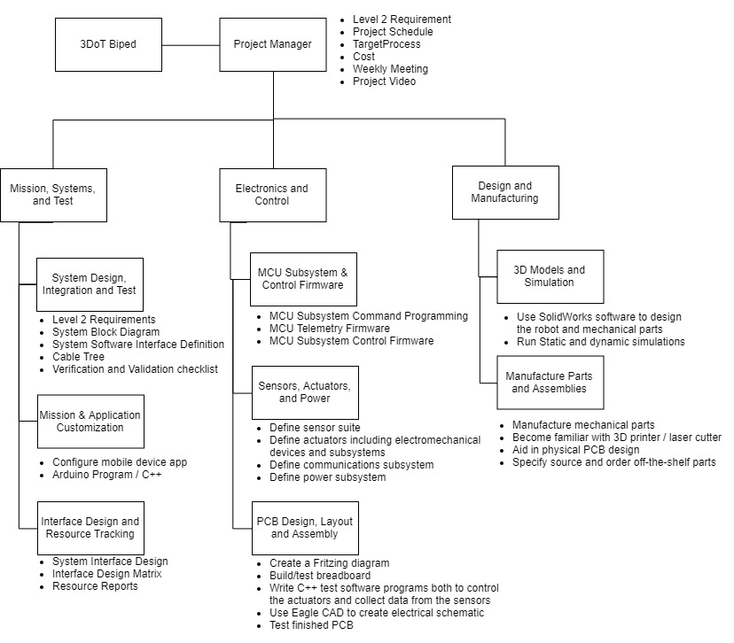
The work breakdown structure helps to visually see the task designated to each member. Each members goals are separated into its own category. This helps to separate their tasks into the categories specify on what exactly needs to be completed. Each category must be organized in a way that just focuses on one topic. For example, for Design and Manufacturing has a category labeled as “3D Models and Simulations”, this goes more into detail with creating the design and using Solidworks to help create a visual representation of it. Solidworks is needed in order to 3D print the parts. So this category only focuses on the design and files needed to 3D print the robots parts which are then created into tasks.
PBS
By: Donovan Minto
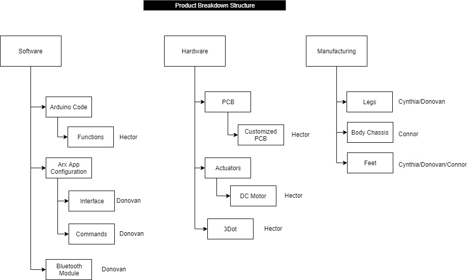
The product breakdowns structure was a vital part in illustrating the specific tasks that were allocated to each division engineer. The individual tasks were broken down from the job description provided, similar to how level 2 requirements flow from level 1. Once the job descriptions were understood, the duties could then be created and delegated to the correct engineers in order for the project to move forward. These tasks could be updated and moved around as the project manager sees fit depending on the critical path of the project. This project relied heavily on the mechanical design of the leg subsystem, so as the semester was closing the tasks that were surrounding the mechanical design of the robot increased, and more engineers were assigned tasks related to such division.
Cost
By: Cynthia Lopez
I have attached the excel sheet to our cost. We added links to where we bought our items for easy access to our materials. We then added a description on why we bought the item. It shows the quantity we bought and how much the item itself costed and what the total amount was with shipping & taxes.
Schedule
By: Cynthia Lopez
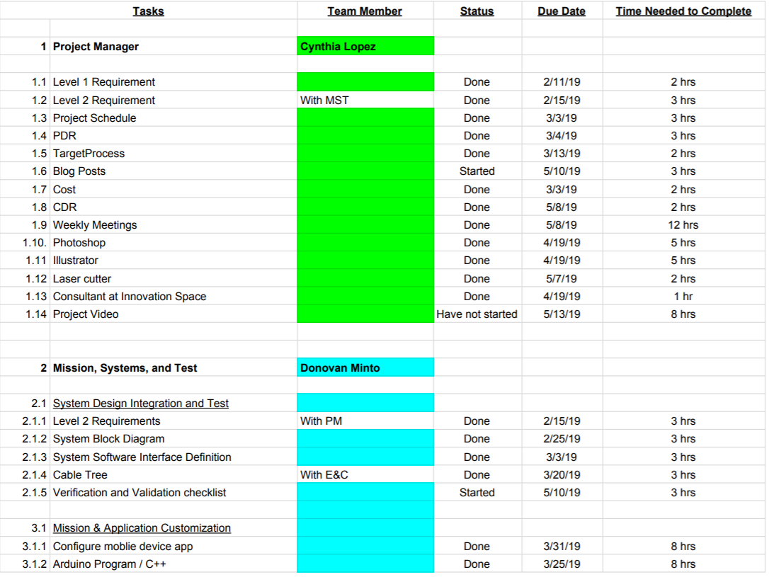
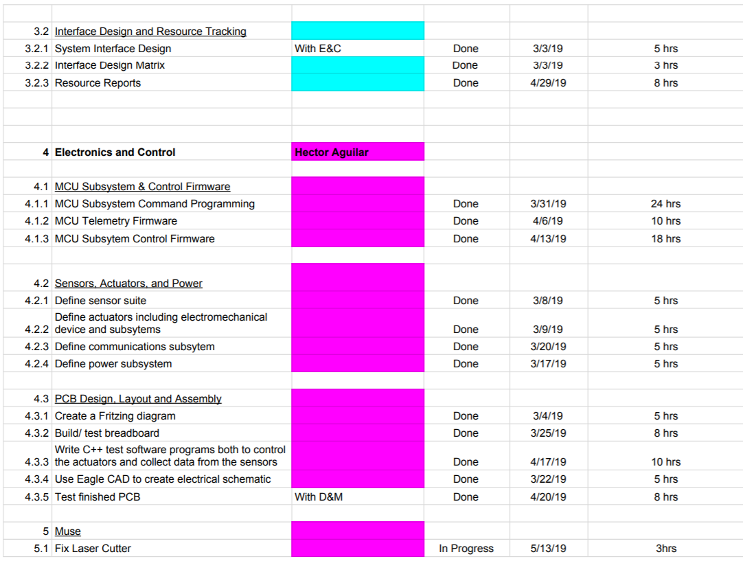
https://docs.google.com/spreadsheets/d/1uDNLLmZNrIz2mGxZ7i7Ko9tlAc9qyB79jHl4bXH2qPQ/edit?usp=sharing
I have attached a link to the excel sheet of the schedule. I have organized it for each team members tasks. It has columns that shows the date the task is due, the amount of time it will take to complete the task and the status of the task. The status ranges from: have not started, started and completed. This helps the project manager to see where each team member is at on their assigned tasks. I also added a column on which team member is assigned to what task, this also allows the project manager to add other team members that can help assist on a certain tasks. For example, Design and Manufacturing is tasked to aid in the physical PCB design and will be working along with the Electronics & Control team member.
Concept and Preliminary Design
Using the 3DoT board’s onboard dual motor drivers, two DC motors will be powered to drive the UCI legs. These legs will be placed on opposite sides of a thin body which will house the 3DoT board sandwiched between the two motors. The 3DoT board will interface the two magnetic encoders to the microcontroller. The motors will drive a crankshaft which then drives each leg, which will create a walking path on the foot. At the foot, prothstetic-like feet will be placed for a stable walk.
Literature Review
By: Cynthia Lopez and Hector Aguilar
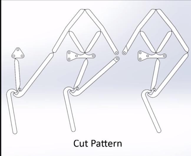
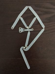
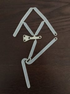
Following the design from UCI’s, we used polypropylene for the material of the leg. There design was intentionally used for a six legged crawler. For our design we will be focusing on one side of the crawlers leg. When looking at the video, two of the legs are connected and are controlled by a single crank for the rotation of the leg. From here we only we will be using the two legs on the far left. The front leg, which is the leg on the left, is being controlled by the crank in the back. The back leg, which is the middle leg, is being controlled by the crank from the front. Even tho the front and back leg looks similar, the back leg has a different characteristic than the front leg. Since it is being controlled by the crank in the front, it has two holes where in the front leg it’s a hinge, these holes are connected to the crank which allows it to rotate.
We had no access to the UCI files so we screenshot from the Youtube video which provided the cut out of the design. From the screenshot, it was then used in Photoshop and illustrator to get the outline of the leg. From here we used Photoshop to get the outline of the design and turn it into vector form.
Screenshot
Front Leg
Back Leg
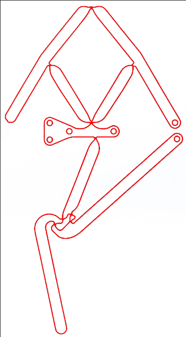
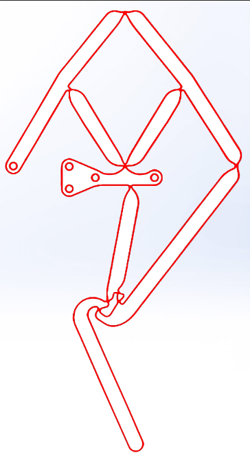
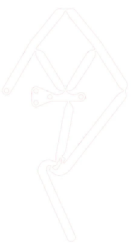
Once we have the file from Photoshop into vector form, we then export it as a EVG file and transport it into illustrator. The purpose of transporting it into illustrator is for the sole purpose of importing the file into the laser cutter. The laser takes AI files and it’s the file the CSULB Innovation Space at the library needs. Once the file is in illustrator it must be in the correct settings that Innovation Space asks for.
Front Leg
Back Leg
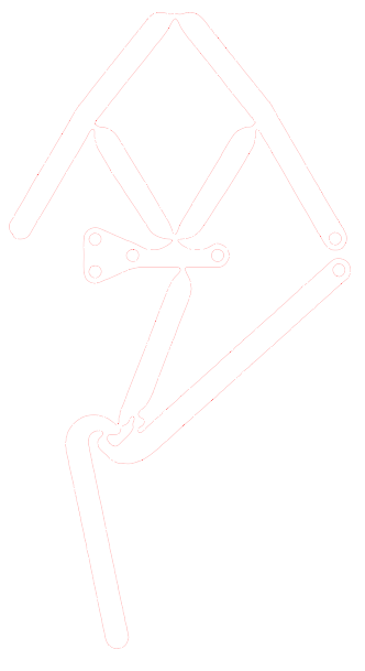
We did multiple prototypes with of this design, since we didn’t have access to the files. There were multiple edits done in Photoshop, in order to get the hinges as flexible as they can be. There were different sizes of the leg created to see which size is best for the hinges to be flexible.
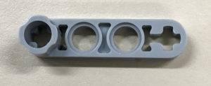
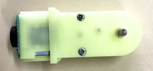
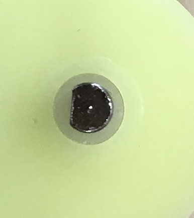
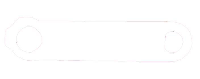
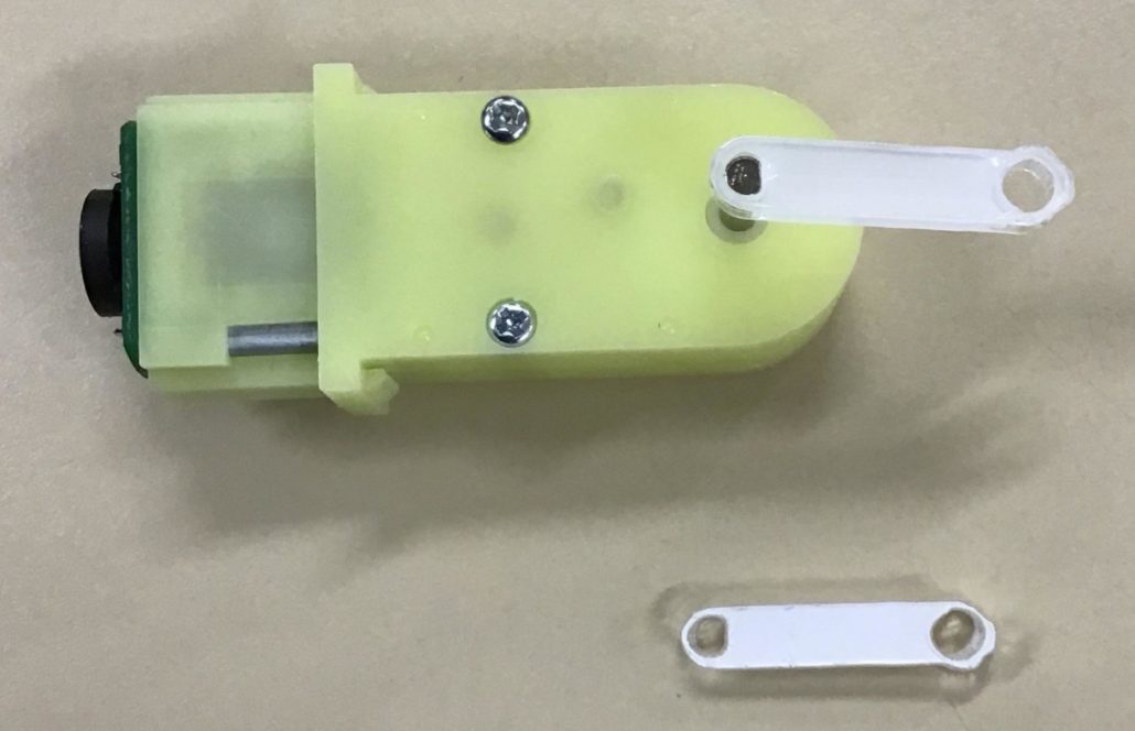
The crank was also laser cut. With the lego crank provide in VEC 415, a photo was taken of it and was then used in photoshop to get the outline shape and mold it in a specific design we wanted. This was also applied to our motors on where it will rotate, by using photoshop we were able to the get the outline of the motors shaft and transfer it into our crank. The purpose of this was so that the motors shaft will fit perfectly in the crank and be able to move the crank without just rotating in the crank itself. We also used the same hole size from the leg and apply it into the crank as well. Therefore we created a crank that can fit into the motor and the leg and will be able to rotate and create the walking mechanism. Acrylic was used for the material of the crank.
Lego
Motor
Motors Shaft
Crank Outline in Illustrator
Crank
Design Innovation
By: Connor Hearn and Hector Aguilar
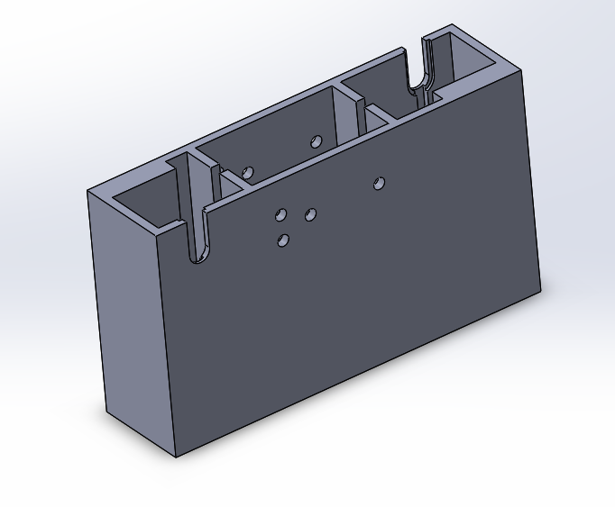
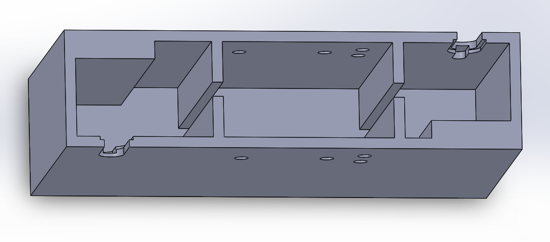
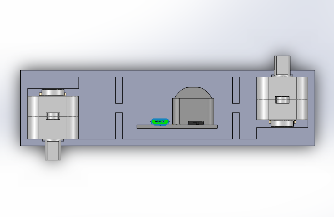
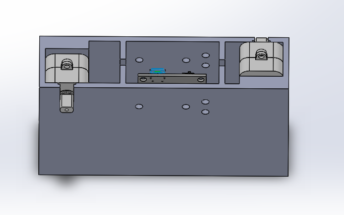
The body will house the motors, 3Dot Board, and pcb. In order to keep the the body’s width thin, slots were made to fit the motor, based on its dimensions, so it can slide in. Some space had to be made on either side of the 3Dot board, for the nuts that will be connected to the bolts that keep the legs in place. The 3Dot board and pcb will be put in the middle slot and the wires from the motors can go through the slots between the partitions.
As opposed to the separate linkages joined by bolts used in the legs of previous semester, we used UCI’s six bar linkage system which keeps the separate links intact, but allows movement through the use of living hinges. The legs can be easily laser cut in less than 20 minutes, when using ⅛ inch thick polypropylene. The thin profile of the legs allow for placing them as close together as possible, perhaps eliminating the need for a weight shifting mechanism.
To help distribute the weight evenly, feet similar to athletic prosthetic legs will be used for an effective and stable walk.
Conceptual Design/Proposed Solution
Using the 3DoT board’s onboard dual motor drivers, two DC motors will be powered to drive the UCI legs. These legs will be placed on opposite sides of a thin body which will house the 3DoT board sandwiched between the two motors. The 3DoT board will interface the two magnetic encoders to the microcontroller. The motors will drive a crankshaft which then drives each leg, which will create a walking path on the foot. At the foot, prothstetic-like feet will be placed for a stable walk.
System Design/Final Design and Results
By: Donovan Minto
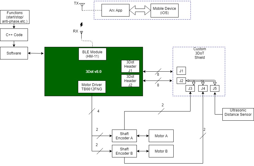
System Block Diagram
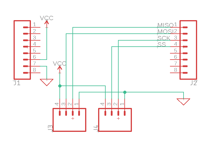
The electronic system block diagram was a system that changed a lot. With the evolution of the project, from one DC motor, to two DC motors, to including a balancing mechanism, to the use of extra motor drivers and servos, the final system block diagram was finally chosen in junction with the customer’s needs. The custom PCB features only external JST connectors to incorporate extra hardware pieces from ultrasonic sensors to LED’s. The 3dot board is the heart of the robot and can handle this whole project without the need of a whole lot of customization. Once this was realized that the 3Dot board can handle the whole project, it came down to deciding how many motors/shaft encoders/servos we would need. It was decided on that we would need only two DC motors with extended shaft encoders to drive both legs of the robot. The other components of the system were trivial and had to be included such as the bluetooth module and Arduino/C++ code.
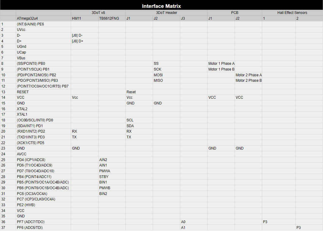
Interface Definition
The interface definition was illustrated with the interface matrix. This tool is often used when describing the pin allocation in embedded system. The system that was designed for this robot was relatively simple in terms of allocating pins due to the simplicity of the custom PCB. The other pins of the three dot can be referenced from the schematic that is provided. The matrix is helpful in terms of seeing what pins are being allocated and what pins are left available to use if necessary.
Modeling/Experimental Results
The modeling that was done for this project was heavily base on the UCI video. The leg design was traced from the video, and into Adobe Photoshop and Illustrator. Once the model was imported into the graphic development software, small tweaks were made in order to get the design of the leg in the correct shape and format to laser cut. Once the first version of the lege was laser cut. Additional tweaks were made and tested for flexibility and durability. The majority of the tweaks were made to the “ligaments” of the legs, the very thin points where the long sections of the leg join each other. Playing with these sections- changing how thin or thick and which joints to manipulate- was part of the iterative design process.
Electronic Design
The 3DoT board at the center of our robot will provide control over the two 180:1 Pololu plastic Gearmotors with an extended shaft to allow for the attachment of magnetic shaft encoders. The shaft encoders will allow us to useya the motor phase code to keep the motors 180° out of phase via firmware, a necessary component to keeping one foot on the ground at all times to demonstrate static walking.
PCB Design
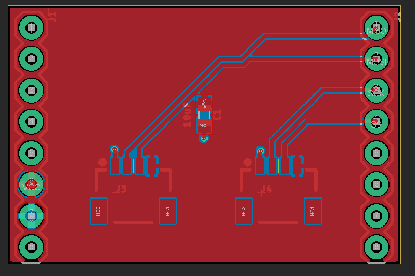
The PCB consists of two 4 pin surface mount JST connectors and a 10 uF supply decoupling capacitor. These components will allow us to neatly interface the logic connections of the motor’s shaft encoder output to the SPI pins on the 3DoT board. The PCB is small, measuring 1250 x 825 mil, it only covers the top shield portion of the 3DoT, so that it does not interfere with the servo, motor, and battery connections directly beneath.
Firmware
Code from EE 444 Hexy by Kyle Kilinski and Brandon Nguyen was used to keep the motors antiphase. This code allows our robot to perform a static walking gait where one foot must remain on the ground at all times.
void setup() {

  Init3DoT();

  attachInterrupt(digitalPinToInterrupt(outAR), countTicksR, CHANGE);

  attachInterrupt(digitalPinToInterrupt(outAL), countTicksL, CHANGE);

  recalib();

  InputR = phaseError;

  SetpointR = 128;        //128 is 50% phase or 180^

  // Turn the PID on

  myPID_R.SetMode(AUTOMATIC);

  //Set min and max output limits on the motor

  myPID_R.SetOutputLimits(maxRightPWM, minRightPWM);

  delay(1000);

}
To perform this, the code first sets both legs to position zero within the recalib() subroutine then the right leg is set to position 180, the absolute encoder count is set to zero at this point.
void recalib() {

  //Sets the left motor to 0^

  do {

    shaftLeft = digitalRead(phaL);

    left_forward();

  } while (shaftLeft);

  left_stop();

  ticksL = 0;

  //Set the right motor to 0^

  do {

    shaftRight = digitalRead(phaR);

    right_forward();

  } while (shaftRight);

  right_stop(); //Stop after in position

  ticksR = 0;   //Reset the tick counter

  //Set the right motor to 180^

  do {

    shaftRight = digitalRead(phaR);

    right_forward();

  } while (ticksR < 360); //Totalticks/2 = 720/2 = 360

  right_stop();

}
The last part of the setup loop sets the maximum PWM output limits for the motor’s speed. Now that the program is in the main loop, the function for moving the robot forward is called.
void loop() {

  forward_phase();

  pastshaftRight = shaftRight;

  pastshaftLeft = shaftLeft;

}
In this function, the motors turn on at whichever pwm value the program had previously calculated, the output of the absolute encoders will be read and assigned to its respective variables.
void forward_phase() {

  all_forward()

  shaftRight = digitalRead(phaR);

  shaftLeft = digitalRead(phaL);

  check_phase();

  if (phaseError < 0) phaseError++;

  phaseError = phaseError * 255;

  //Serial.println(phaseError);

  InputR = phaseError;

  myPID_R.Compute();

  rightPWM = OutputR;

}
check_phase is called, which calculates the phase error that will be corrected with the PID controller. Once we’re back in the forward_phase() subroutine, we compute the PWM value to drive the right motor either slower or faster to keep out of phase with the left motor.
void check_phase() {

  phaseRight = ticksR / totalTicks;

  phaseLeft = ticksL / totalTicks;

  if (abs(phaseLeft - phaseRight) > 0.5) {

    if (phaseLeft > phaseRight) {

      phaseRight += 1;

    }

    else {

      phaseLeft += 1;

    }

  }

  phaseError = phaseRight - phaseLeft;

}
The program will continue to the main loop and repeat the process over again .
Mechanical/Hardware Design
By: Connor Hearn
The body for the biped is a barebones design that is able to hold the motors and 3Dot board, and connect to the legs to allow it to stand and walk. Partitions were made to separate the motors from the 3Dot board. Cuts were made in the partitions to allow the motor wires to be connected to the 3Dot board. The body of the biped needed to be as thin as possible to improve its performance. The wider the body is, the harder it is for the biped to walk and balance. The legs will be bolted into the side of the body and its position is indicated by the holes. The nuts that secure the bolts from the legs in place, will occupy space within the section of the body that houses the 3Dot board. Because the nuts prevent the 3Dot board from touching the walls of the body, there wasn’t a clear or easy way to try to secure the 3Dot board in place. Depending on the size of the nuts, it could be enough keep the 3Dot board in place. The sections that house the motors were made based off of the size of the original 90 degree gear motors. To prevent the body from getting wider, the motors will slide into the body rather than having the motor and its shaft have to be able to fit in. The motor shafts will slide through the slits made on the ends of the body, that allow it to be suspended, leaving space below for the addition and implementation of the shaft encoders.
The body was also designed to have legs on both sides. If you look closely on the design there are holes, which is where the motors be slide in. From the motors shaft the crank will be connected to it and the legs. Now the holes are placed on different sides of the body. The reason for that it what was discussed before in the literature review. The front and the back leg look similar but the difference is, the back leg has two holes which is where the crank will be attached. When you look in the video you can see that the front and the back leg are cranked in different positions. So this is the reason we design our body this way, so it takes into consideration of the way both of the legs are designed. As shown in the photo above.
Verification & Validation Test Plan
By: Donovan Minto
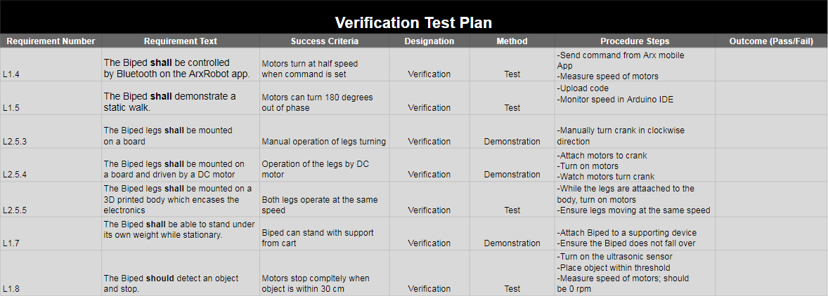
The verification test plan was very tricky to nail down. The main goal of the test plan was to answer the question,”was the right product built?” The goal was to verify each of the level 1 requirements to ensure proper operation of the project. The test plan is broken down into separate test cases that can test a single requirement, or a test case can group multiple requirements that are similar together and test them all together. The main components that needed to be tested for the Biped was the leg mechanism, the motor phase code, and the simple connectivity of the 3Dot through the Arx robot App.
Concluding Thoughts and Future Work
By: Cynthia Lopez
The next generation could make improvements on this project. Definitely understand what the customer wants and keep them updated on your project. The customer may disapprove on some aspects on your project and would be best to be on the same page as the customer. The customer may make changes that will affect the project, so definitely keep them updated so the changes can be made ahead of time.
I would first recommend to create a design and make it your official design for the project, small changes may occur but be sure you make no major changes to it. I would second recommend to understand the basics in Adobe Photoshop and Illustrator, along with Solidworks. These are the main software that are necessary in order to create the leg. Third recommendation is to create the leg into Solidworks, either use the Illustrator file we have and import into Solidworks or start from scratch. The purpose for converting it into Solidworks is so that the student can try to 3D print the leg and see if it’s a better alternative than the polypropylene material used prior. If so, this approach would be best recommended since the polypropylene material is easily broken around the hinges /or ligaments. If you are still using polypropylene, make sure you use protective tape or masking tape to prevent the material melting. If this step is not taken into consideration then the design will be affected by the melted material. I would recommend to take an advantage of the engineering tutoring center and ask MAE tutors for help if stuck on Solidworks. The fourth recommendation is to make sure you know what is needed for your robot to work. Do research on the electronics you will need for your project and make sure you do tests to them so make sure they are the appropriate materials needed to more forward. Also, time management and communication is crucial when involved in any project that requires teamwork. Making sure everyone is completely their tasks on time will help the project move forward. Communication is necessary in order to have a knowledge on where each team member is at on their tasks and when they are available to contribute on the project.
By: Connor Hearn
In the future, the body will have to be changed to fit the new motors that want to be used. Additionally, a way to secure the 3Dot board within the body, will need to be figured out. Depending on the size of the legs that want to be used, the position of the holes to secure the legs to the body and the position of the motors would need to be changed accordingly.
By: Hector Aguilar
The bare-bones concept of this robot has been built and tested, and is ready for further development. The following generations should focus on adapting this concept to a body or chassis, since we were not able to do this due to time constraints. Moving this project into its next phase, there should be more tests, back of the envelope calculations, and trade off studies to help this project to completion. Given this is an electrical engineering project, the mechanical aspect of this project may slow down the progress of it. We emphasize that a level of comfort with solidworks should be achieved early on in the semester in order to design the necessary components. Our mission was to create a robot that could walk, turn, and avoid obstacles. In order to achieve these goals in the future, one should present their solutions to the instructor, or other design resources, early on in the development of the project, since these problems require creative solutions that cannot be designed in just one iteration.
References/Resources
- Project Video
- Photoshop and Illustrator for Laser Cutting
- View Access to all Positions Folder Drive
- Leg Design Drive Link
- Three Legged Walking Module
- Alternating Tripod Gait Compliant Leg Mechanism
- Mark Plecnick’s Leg Mechanism
- Motor Trade-Off Study
- Biped Body Solidworks Models
- Hall Effect Sensor Test


