Spring 2016: 3DoT David PCB Design
BY: Kent Hayes (Electronics and Control)
Introduction:
In order to create the PCB for our 3DoT David, we needed to know what areas the 3DoT board would be lacking. It turns out that the board would not have a signal processing circuit for our Infrared system, a speaker, and phase detection circuit. Therefore, all we needed to do was design an OP-amp comparator with hysteresis (Schmitt Trigger) in order to create a threshold for voltages that we would find acceptable. In addition we designed voltage buffers and hooked them up with flex sensors for the phase detection circuit.
Related requirements:
As a part of the subsystem requirements:
- The 3DoT David shall use an infrared LED emitter and infrared detector for the tagging system in the game of tag.
- The 3DoT David shall use a small speaker to produce the buzzing sounds to indicate the end of a round in the game of tag.
- The 3DoT David shall include a PCB that uses a Schmitt Trigger circuit to convert the analog output from the IR detector into a digital output to be handled by the 3DoT board. It will also have a voltage follower and anti-aliasing filter for the synchronization of the two motors. This PCB shall also provide the connections from the 3DoT board to the peripherals such as the IR emitter, IR detector, and micro motors.
In order to complete this requirement we will being going over each part of the PCB schematic that contributes to fulfilling it.
Signal Processing Circuit (Schmitt Trigger)
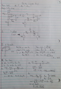
The Schmitt Trigger is able to clean up messy signals received from the IR detector and only accept input values that it will recognize as high or low values which will be defined as the threshold. This is important for our game of tag because we do not want just any voltage reading to register as being hit. Based on the voltage values being read at various distances, we can then properly set the threshold values. The threshold is will change by varying the resistor values and the Vcc. The following image is a picture of the calculations made by Kent (Electronics and Control engineer) for the design on the Schmitt Trigger resistor values.
(Fig. 1 Hand written calculation for voltage threshold)
These calculations were done with the thought of the threshold voltages being 3.3V and 5V, which, according to Jeffrey (E&C division manager) is incorrect because threshold voltages should be nowhere near the supply voltages. Once Kent conducted the test on the IR emitter/detector, he found more realistic values for the threshold which are 2V and 3V. Using these two values, he re-did the calculation and got the resistor values to be R2 = 10k and R5 = Rhys = 20k. We then multiplied the values by 10 to make sure there would not be much current going through the circuit. Here is a result of the final circuit done in EagleCAD: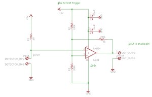
(Fig. 2: PCB Schematic of Schmitt trigger)
BJT Inverter (IR emitter driver)
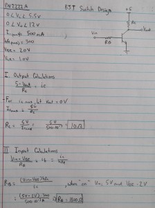
The next part of the PCB that needed to be designed was the BJT inverter for driving the current for the IR emitter. The following is a picture of the calculations made by Kent for our design:
(Fig. 3: Hand written calculations for BJT inverter)
After doing the calculations, he asked Jeff to check his work for mistakes, to which Jeff said that the IcMax was not the correct value taken from the data-sheet. It should be the typical forward current of the IR LED instead of the BJT. After looking at the data-sheet for the IR LED, he found the Ic value to be 50mA instead of 500mA. In addition, the source voltage coming from the collector side should be the forward voltage of the IR LED (1.35V) and not the VCC of the 3DoT board (5V). Finally, Jeff explained that Vbe should always be around 0.7V when doing designs. After making these changes, Rb = 3.9k and Rc = 68. The following is a circuit from the resulting calculations:
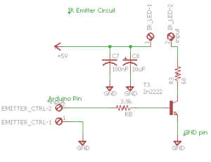
(Fig. 4: PCB Schematic of BJT Inverter)
Speaker Circuit:
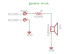
Since we wish to implement a hit count system, we have decided to use a piezo speaker. It will have a resistance value that is inversely proportional to how loud the speaker will be. The following is a picture is of the circuit:
(Fig. 5: PCB Schematic of Speaker Circuit)
Motor Phase Detection/Correction (Flex Sensor Resistor)
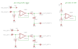
The final part of our schematic is the motor phase detection. It includes an anti-aliasing filter and a flex sensor that acts as a potentiometer in the voltage divider. Our new mechanical design of the spider calls for the addition of a phase correction circuit. We are no longer controlling all of the legs with one motor and the head with the other, but instead we have separate motors controlling either the left or the right side. We plan for both motors to power on when a command to go forward/backward is entered, and for only one side to power on when wishing to turn left or right. After performing the command for turning left or right, the legs may not be aligned when wishing to go forward. This is why we wish to implement a circuit that can track the phase of each motor in order to determine if they are in or out of sync. The flex sensor changes its resistance the more it is bent (See FSR test blog post), therefore with the help of Chris (3DoT David Systems) and Jeff( E&C Division manager), Kent was able to create a voltage divider with these flex sensors. We can then measure the voltage from the voltage divider of both sides and if they are not close enough, we will say they are out of phase. The OP amp that we are using is the LM324 series which is a quad OP amp package. We only had use for 3 of them so the last OP amp is connected such that it will not be using any power. The following image is of the voltage buffer circuit:
(Fig. 6: PCB Schematic of FSR correction)
Conclusion:
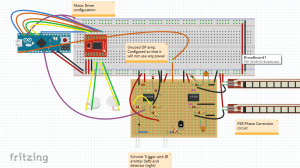
Since we have incorporated the Schmitt trigger, BJT inverter, speaker, and motor phase correction in the final PCB schematic, we will be able to meet the different system requirements with which we were given. The following page shows an image of a fritzing diagram of the entire electrical system with which we are working and includes:
- Sparkfun Pro Micro (32u4 microcontroller on 3DoT Board)
- Sparkfun TB6612FNG motor driver( IC will be on the 3DoT Board)
- Schmitt Trigger
- IR emitter/detector
- Voltage buffer with FSR for phase correction
(Fig. 7: Full View of Electrical System)

