3DoT Motor Driver Tutorial
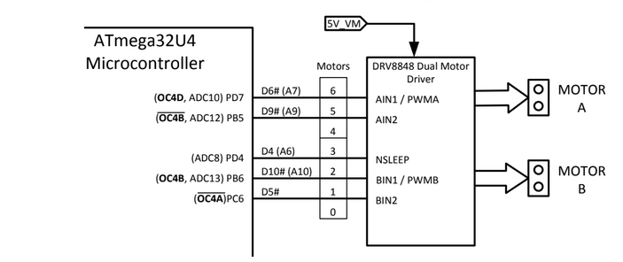
3DoT Boards v9.1+ have a built in DRV8848 motor driver. For the experienced engineer, the DRV8848 datasheet and 3DoT Block Diagram might be enough information alone to program the motors on a 3DoT.
For the rest of us, let’s step through how to use the motor driver using the information from these documents.
How do we control the motors using AIN1, AIN2, NSLEEP, BIN1 and BIN2? Let’s check the DRV8848 datasheet.
(For those interested, read more about why this table is named “Bridge Control”)
In this table, “xIN1” means either AIN1 or BIN1. “xOUT1” and “xOUT2” are the output pins to the motors.
What we can tell from this is that if we set AIN1 to 1 and AIN2 to 0, the motor will spin in the forward direction. give it a try!
void setup() {
  pinMode(6, OUTPUT);
  pinMode(9, OUTPUT);
}

void loop() {
  digitalWrite(6, HIGH);
  digitalWrite(9, LOW);
}
In this quick and dirty code, I set digital pins 6 and 9 to outputs and write a HIGH (1) and LOW (0) to each respectively.
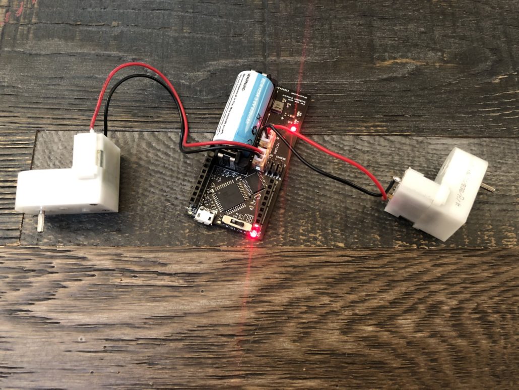
Upload this code and plug in motor A. You should see it spinning at maximum speed!
Next, you can reverse the HIGH and LOW to make the motor spin in the opposite direction. It’s that simple.
Speed Control
In order to make the motors run at a speed other than full speed, the same HIGH/LOW logic should be applied, although the duty cycle of the HIGH input will decide the speed of the motor.
In Arduino, we can control the duty cycle to a pin using the analogWrite(pin, value) function. The value passed to the analogWrite() function should be a number between 0 and 255, where 255 is 100% duty cycle, and 0 is equivalent to digitalWrite(pin, LOW).
Let’s run our motor at roughly half speed.
void setup() {
  pinMode(6, OUTPUT);
  pinMode(9, OUTPUT);
}

void loop() {
  analogWrite(6, 128);
  digitalWrite(9, LOW);
}
As you can see, all I changed was the line writing a HIGH to AIN1. Instead of a HIGH, I wrote a 50% duty cycle signal to AIN1, which should make your motor spin at about half speed.


