3DoT ScrewDriver Generation 1 Summary Blog Post
Author/s: Saba Theodory (Electronics and control) and Christian Pla (Design and manufacturing)
Table of Contents
Executive Summary
You always hear the statement “you don’t have to reinvent the wheel” and think to yourself, that’s probably true. Well for the 3DoT ScrewDriver that is exactly what we did. The ScrewDriver is named as such because its “wheels” are actually screws. The threaded pattern will propel the robot in a vertically or the screws can just roll allowing faster horizontal movement speeds. The 3DoT board controls all the functionality and allows for Bluetooth capabilities. That means you could take the ScrewDriver off-road and have it drive through the sand or even rip through your grass all at the convenience of your Bluetooth enabled phone.
Program and Project Objectives
Program Objectives
The Robot Company (TRC) will be debuting its 2019 line-up of toy robots and associated games at the Toy-Invasion 2019 convention in Burbank CA on January 6, 2019. Your team’s assignment is to make the 3D printed and/or laser-cut prototypes to be showcased at the convention, prior to production starting in the second quarter of 2019. The robots will feature our new ArxRobot smart phone application and the Arxterra internet applications allowing children to interact and play games around the world. In addition, the robots should be able operate autonomously in game mode. See game(s) (i.e, mission objectives) assigned to your robot by the Game Division. To decrease electronics cost, interoperability between all TRC robots will be maintained by incorporation of the 3DoT board, developed by our Electronics R&D Section. Modification of downloadable content is limited to software switch setting and robot unique graphics of the smart phone and Arxterra applications. Modifications of electronics is limited to custom 3DoT shields as required by the unique project objectives of your robot. The Marketing Division has set our target demographic as children between the ages of 7 and 13, with a median (target) age of 11. To decrease production costs, please keep robots as small as possible, consistent with our other objectives. As with all our products, all safety, environmental, and other applicable standards shall be met. Remember, all children, including the disabled are our most important stakeholders. Our Manufacturing Division has also asked me to remind you that Manufacturability and Repairability best practices must be followed.
Project Objectives
The ScrewDriver aims to provide a new outlook on movement. The screw wheels by nature enable the robot to tackle rough terrain and go over obstacles that would otherwise be difficult to overcome. The screw wheels provide a new and fresh train of thought when it comes to the physics of motion. In addition, the ScrewDriver uses the 3DoT board v8 which allows for easy-to-use Bluetooth capabilities. The circuitry can easily be upgraded to include sensors or actuators. The 3D model is extremely small meaning that rebuilding it in the future would be cheap and easy.
Mission Profile
The mission objective of the ScrewDriver is to create a relatively off-road capable robot that could fit in the palm of your hand while employing screws rather than wheels for movement. The mission itself will be an on-campus course near the traffic circle. The course will have soil and rocks and the robot should be able to go over it while being controlled through the ArxRobot mobile application.
The full details of the mission can be found here.
Project Features
The ScrewDriver major features include:
Easy Assembly and Disassembly
- The pulleys are 3D printed so the user will not have to purchase any.
- The motor mount holes are placed in the correct spot with the same hole size as the screw that comes with the motor mounts.
- The cover has nut catches to easily install and remove the cover without requiring a pair of pliers to hold the nut in place.
- The pulleys have a D shaped hole to allow the motors to bolt on without being loose.
- The 3DoT board slides into a track for easy removal and installation.
Intuitive User Interface
- The robot can be controlled by any Bluetooth enabled phone using the ArxRobot mobile application.
- The ArxRobot application is intuitive and straight forward allowing the user to easily connect to the robot and start controlling it.
Accessible Anywhere
- The robot can be controlled using the Arxterra control panel so commands can be sent to it from anywhere in the world as long as there is WiFi.
Comes in a small package
- The robot barely exceeds the size of a 3DoT board, so it is extremely small and easy to carry around.
- The robot is cheap and easy to 3D print, hence it can be produced in large numbers with ease.
- The battery life is a little below 2 hours since its weight doesn’t hold it back
Ultimate Versatility
- The screw “wheels” allow the robot to traverse a variety of terrains including soil, sand, loose dirt and grass.
- The cupola on top allows the driver to select any direction they like as forward since the windows are omnidirectional.
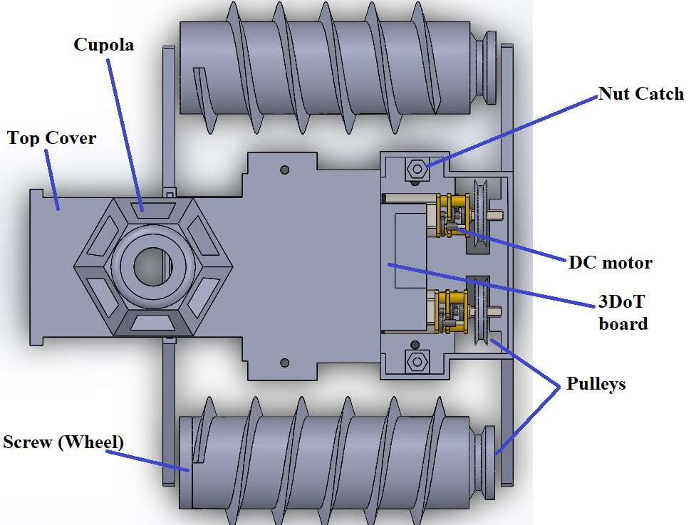
Figure 1: 3D model with cover off with all the major mechanical and electrical subsystems displayed.
Requirements
The level 1 requirements of Screw-Driver are based on the customer’s specifications regarding the robot’s propulsion method, constraints, program objectives, mission profile, and aesthetics. From an ongoing and iterative design process with our team’s engineers and the customer, these requirements have eventually been made quantitative and physically realizable. In order to fulfill these expectations, the robot’s required technical features are later outlined in its level 2 requirements.
Engineering Standards and Constraints
- IEEE 29148-2018 – ISO/IEC/IEEE Approved Draft International Standard – Systems and Software Engineering — Life Cycle Processes –Requirements Engineering.
- NASA/SP-2007-6105 Rev1 – Systems Engineering Handbook
- Bluetooth Special Interest Group (SIG) Standard (supersedes IEEE 802.15.1)
- C++ standard (ISO/IEC 14882:1998)
- Federal Communications Commission (FCC) Relevant standards for a product implementing a 2.4GHz radio, FCC Intentional Radiators (Radio) Part 15C, and Unintentional Radiators FCC Part 15B for CPU, memories etc.
- NXP Semiconductor, UM10204, I2C-bus specification and user manual.
- ATmega16U4/ATmega32U4, 8-bit Microcontroller with 16/32K bytes of ISP Flash and USB Controller datasheet section datasheet, Section 18, USART.
- USB 2.0 Specification released on April 27, 2000, usb_20_20180904.zip
- Motorola’s SPI Block Guide V03.06
Program Level 1 Requirements
Cost:
L1.15 The Screw Driver shall cost under $250
L1.16 To demonstrate the Screw Driver’s durability, it should withstand a drop of 1.4 meters.
Extensibility:
L1.17 The Screw Driver should employ a custom PCB to make use of the 3DoT board’s extensibility so extra sensors can be added in future generations of the robot
Maintainability:
L1.18 Disassemble and Reassemble of the Screw Driver shall be constrained to less than 20 minutes (10 minutes+10 minutes). “Disassembly: The 3Dot board is clear of all other electronic and mechanical subassemblies. All electronic and mechanical subassemblies and associated connectors, sensors, and actuators including motors are disconnected. A functional test of the robot is conducted after reassembly to confirm its functionality. All project may reference a cable tree as well as an assembly diagram as necessary. This requirement is demonstrated/verified on the last day of the schedule.”
Schedule:
L 1.19 The Screw Driver shall be completed by the date of the final: May 14th 2019.
Accessibility:
L 1.20 Accessibility by the blind and Marketability of the robots should be implemented/enhanced by a speaker.
L2.20 The speaker should generate the sound effect of a drill to let the user know when the robot is moving
Aesthetics:
L 1.21 The robot shall be designed in such a way that there are no dangling or exposed wires.
Usability:
L 1.22 The usability of the Screw Driver shall be enhanced by use of the Arxterra phone and control panel application as dictated by the assigned mission.
Manufacturability:
L 1.23 Constructability of 3DoT robots shall be documented at the CDR and approved by the president of the TRC robot company. Constraints imposed by this requirement include the use of bushing or bearings in all moving and rotating parts. Interlocking Hinges with latching mechanism. No gaps greater than 1 millimeter, and immediate access to all external connectors (USB, switches).
L 1.24 The Size of the electronics enclosure, shall be constrained to be no greater than the 3DoT board, 3DoT shield(s), and associated mounting hardware.
L 1.25 Power to all 3D robots shall be provided by the 3.7V RCR123A battery included with the 3DoT board or use of the external battery 2.0mm PH series JST connector located on the 3DoT board. The RCR123A is a Lithium Polymer LiPo battery. All Safety regulations as defined in Section 4.3 Hazards and Failure Analysis of this document shall apply to the shipping, handling, storage, and disposal of LiPo batteries.
L 1.26 Back of the envelope calculations and experiments shall be conducted to set the diameter of Power carrying wires. Follow the American Wire Gauge (AWG) standard when defining the diameter of power carrying wires.
Functional:
L 1.27 All 3DoT robots shall incorporate the 3DoT v8 or later series of boards.
L 1.28 Software shall be written in the Arduino De facto Standard scripting language and/or using the GCC C++ programming language, which is implements the ISO C++ standard (ISO/IEC 14882:1998) published in 1998, and the 2011 and 2014 revisions.
L 1.29 bAll 3DoT robots shall be in compliance with the 3DoT Command and Telemetry Packet specification.
L 1.30 All 3DoT robots shall be controlled via Bluetooth 4.0 in compliance with the Bluetooth Special Interest Group (SIG) Standard (supersedes IEEE 802.15.1).
Environmental Health and Safety (EH&S) Standards:
L 1.31 All standards, codes, and regulations as defined in the “Engineering Standards and Constraints” Section of this document shall apply to the Screw-Driver.
L 1.32 All Lithium (Li-ion, Li-polymer) batteries shall be purchased with and stored, when not in use, in a fire and explosion proof battery bag.
Project Level 1 Functional Requirements
L1.1 The robot will have two independent propelling screws.
L1.2 The robot’s chassis and screws will be 3D modelled and printed.
L1.3 The robot shall be able to drive through the course without a large amount of dirt getting stuck between the threads of the screws.
L1.4 The robot shall be able traverse over soil, small branches and twigs present in the course defined in the mission profile.
L1.5 The robot should be able to traverse over obstacles up to 0.25 inch in diameter found in the course.
L1.6 The robot shall be stable enough to exceed an elevation angle of 55 degrees from the ground when traversing through the course.
L1.7 The robot shall be able to turn in place.
L1.8 The robot shall be able to move parallel to the axis of rotation on loose surfaces such as sand.
L1.9 The robot shall be able to move perpendicular to the axis of rotation.
L1.10 The robot shall be able to communicate with the operator’s Bluetooth device via the Arxterra app.
L1.11 The robot shall go through the course described in the mission profile.
L1.12 The screws will be driven by DC motors.
L1.13 The robot’s controlling circuitry will be contained in the chassis.
L1.14 The robot will use the 3DoT board for controlling the motors.
L1.15 Project shall be safe to operate, as determined by the CSULB COE Health and Safety Policy.
System/Subsystem/Specifications Level 2 Requirements
L2.1.1 The final robot will have two screws of the length of 3.42 inches and diameter 1.5 inches
L2.1.2 The screws will be printed with oppositely threaded notches.
L2.2.1 The 3-3-3 rule shall be followed when printing the screws unless printed at the library.
L2.2.2 The 3-3-3 rule shall be followed when printing the chassis unless printed at the library.
L2.2.3 The screws and chassis will be 3D printed out of ABS plastic.
L2.3.1 The screws will have a large enough pitch of 0.5 inches between the threads making it difficult for soil to be trapped between notches.
L2.4.1 The DC motors will have a rated torque of 0.7 kg.cm to provide enough torque for the screws to traverse over various obstacles on the course.
L2.4.2 The gear ratio from the motors to the screws shall be 1:1 to prevent any speed loss.
L2.5.1 The diameter of the screws will be 1.5 inches allowing it to go over objects smaller than that.
L2.6.1 The distance between the screws will be 2.85 inches giving it a wide base.
L2.6.2 The center of mass of the robot shall be located near the bottom since the screws and motors are near the bottom.
L2.10.1 The Bluetooth commands shall be received via the HM-11 Bluetooth module.
L2.11.1 The robot shall be tested on a predefined course on campus containing branches, soil, and twigs.
L2.12.1 The motors for the final robot will be DC 6V 155 RPM 100:1.
L2.12.2 The robot’s motors will be driven by the TB6612FNG motor driver.
L2.13.1 The robot will be driven by motors small enough to fit in the chassis.
Subsystem A (e.g. Mission) Requirements
Mission:
The battery life shall last the duration of the mission with a safety factor of 2x.
Electronics:
The ScrewDriver will use the 3DoT board to control all on board electronics.
The battery will be 3.6V RCR123A
Software:
The control commands will be sent via the ArxRobot app and the Arxterra Control Panel
Mechanical/Manufacturing:
The ScrewDriver dimensions will not exceed the size of the 3DoT board and the motors
Allocated Requirements / System Resource Reports
The ScrewDriver has had a prototype and final both designed and printed differently. Both required different allocations since they were drastically different in size, motors and electronics. Since the focus is shifted to the final project, the following mass and power allocations are for the final robot while the cost will cover both the prototype and final.
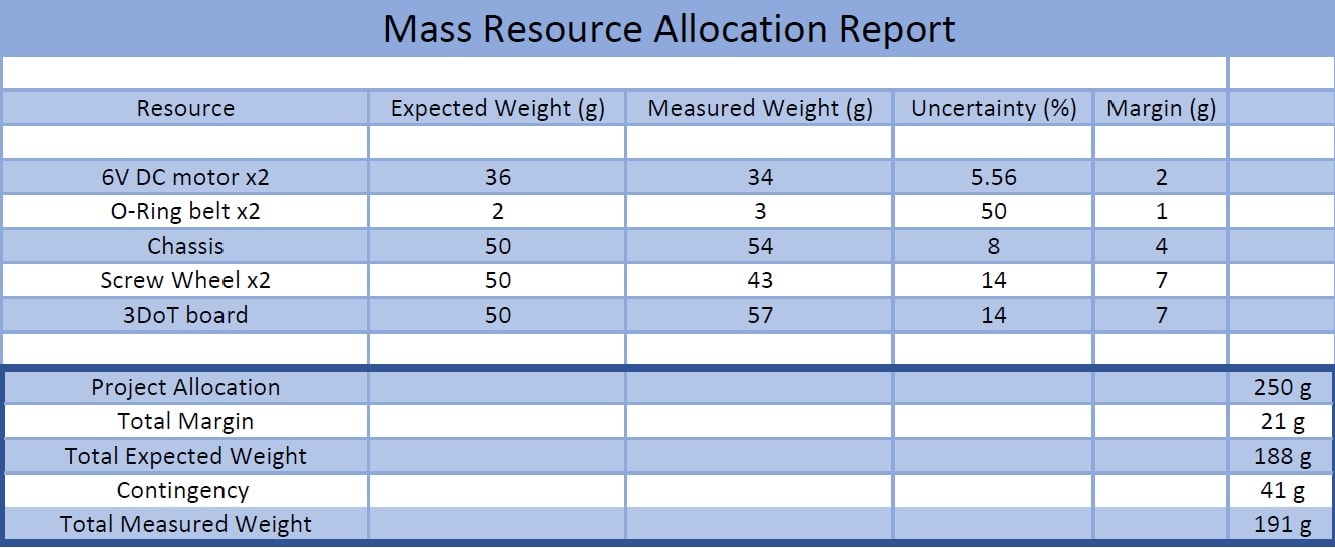
Figure 2: The rated torque of our 6V DC motors is 0.7 kg.cm meaning that it can lift 700 g 1 cm. By choosing 250 g as our mass allocation we ensure that the motors can easily support the weight of the robot and have enough propelling force to overcome rough terrain without getting stuck due to being too heavy.
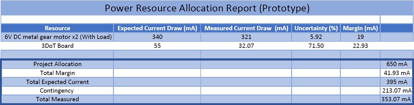
Figure 3: We selected the battery size as 650 mAh since the 3DoT board has that built in. We don’t require a larger battery because our total current draw is 353.07 mA meaning that the battery can theoretically support the robot for 1.84 hours. The robot will need much less time to finish the mission course as shown here.
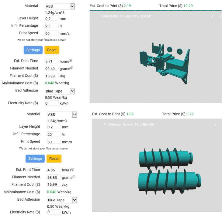
Figure 4 :This shows the STL files sliced to calculate the estimated print time and weight. Displayed here are both the chassis and screws.
Chassis
Estimated Cost: $10.29
Estimated ABS Filament Needed: 99.49 grams
Estimated Print Time: 5.71 hours
Screws
Estimated Cost: $9.77
Estimated ABS Filament Needed: 68.83 grams
Estimated Print Time: 4.86 hours
Complete Design
Total Estimated Cost: $20.06
Total Mass: 0.168 kg
Total Estimated Print Time: 10.57 hours
Project Report
The assigned project schedule was followed for the most part and the project is progressing as schedule and hence should be complete on time as scheduled.
Project WBS and PBS
The PBS shown below is broken up into two main parts: The chassis and the screws. The screws will only involve 3D modeling and printing them as well as find a way to attach them to the chassis. The chassis will involve both a manufacturing and an electronics component. The electronics component involves the motors, microcontroller and Bluetooth communication. The belt and pulley system will involve the power transfer from the motors to the screws.
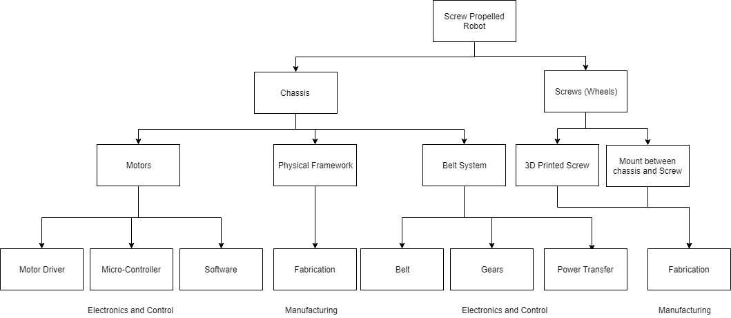
Figure 5: This block diagram shows the product breakdown structure of the ScrewDriver
The WBS below shows the work overview done throughout the semester to have the ScrewDriver built and successfully complete the mission. The electronics and control engineer is responsible for the motors and any electronics or applications involved in controlling them while the design and manufacturing engineer is responsible for the 3D modeling, 3D printing and assembly component of the robot.
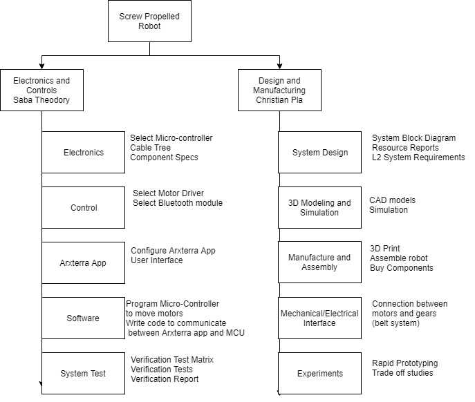
Figure 6: The block diagram show the work breakdown schedule over the entire semster.
Cost
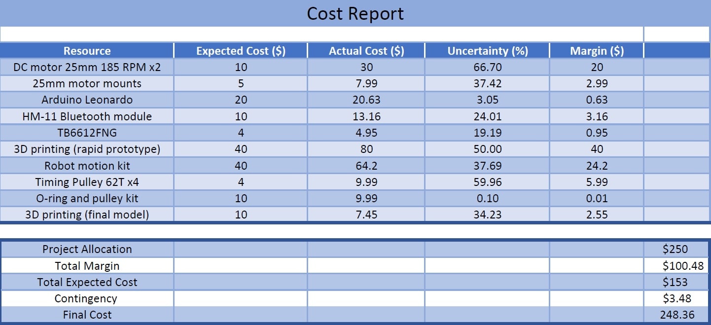
Figure 7: Cost report for the 3DoT ScrewDriver. Most of the cost was due to building the prototype. Since testing had to be done quickly all the separate components of the 3DoT board needed to be purchased quickly. The final robot however, is significantly smaller and all that needs to be purchased is a pulley kit and the motors because the 3DoT board puts all the required electronics on a small PCB. The motors are not included in the cost report because they were already purchased and not used in a previous semester.
Schedule
The project schedule below shows the progress of the project from the beginning. The project schedule is being followed diligently and the robot should be complete before the day of the final.
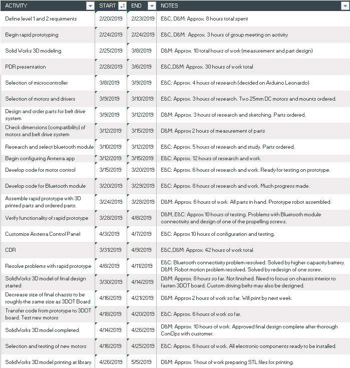
Figure 8: The project schedule along with logged hours is shown in this figure.
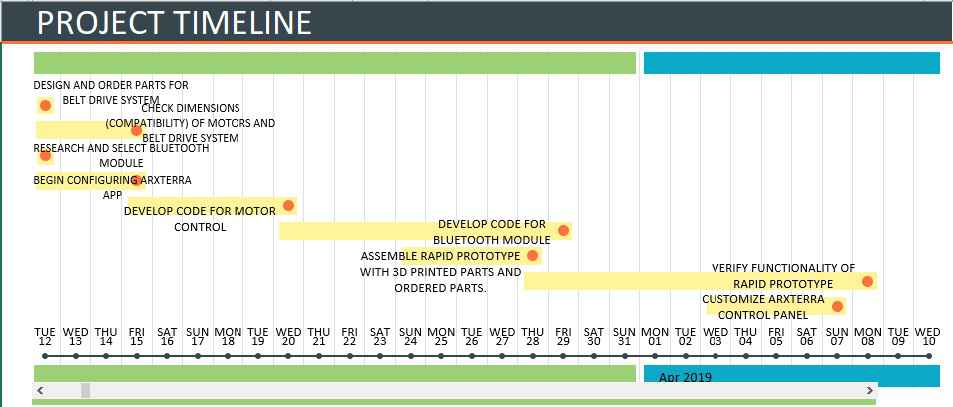
Figure 9: Projected critical path of the project
The critical path of the project is shown above and it illustrates how many tasks were performed in parallel to get to this point of completion.
Burndown and/or Percent Complete
| TASK | STATUS |
| RESEARCH | COMPLETE |
| CAD MODELING (PROTOTYPE) | COMPLETE |
| SELECTING MOTORS | COMPLETE |
| SELECTING MICROCONTROLLER | COMPLETE |
| CODE FOR DC MOTOR CONTROL | COMPLETE |
| TESTING CURRENT DRAW OF COMPONENTS | COMPLETE |
| BLUETOOTH CONTROL CODE | COMPLETE |
| CONFIGURE ARXTERRA APP | COMPLETE |
| ADDING CUSTOM AVATAR TO CONTROL PANEL | COMPLETE |
| CUSTOMIZING ARXTERRA CONTROL PANEL | COMPLETE |
| PURCHASING PARTS FOR PROTOTYPE | COMPLETE |
| ASSEMBLING PROTOTYPE | COMPLETE |
| TESTING PROTOTYPE | COMPLETE |
| TESTING TOTAL CURRENT DRAW | COMPLETE |
| CAD MODELING (FINAL DESIGN) | COMPLETE |
| SELECTING MOTORS (FINAL DESIGN) | COMPLETE |
| SELECTING PARTS FOR FINAL DESIGN | COMPLETE |
| SELECTING ELECTRONICS (3DOT, AND MOTORS) | COMPLETE |
| MEASURING CURRENT DRAW OF COMPONENTS | COMPLETE |
| ASSEMBLY OF FINAL DESIGN | COMPLETE |
| TESTING FINAL DESIGN | COMPLETE |
| TESTING CURRENT DRAW OF FINAL DESIGN | COMPLETE |
| PERCENTAGE COMPLETED: | 25/25 = 100% |
Concept and Preliminary Design
The ScrewDriver has gone through many iterations conceptually, but only two of those concepts were printed and actually came to life. The prototype was the bigger, bulkier version while the final design is the small, agile version that uses the 3DoT board for control.
Literature Review
Screw-Driver was the first of its generation, so obviously no literature could be found for research on the Arxterra Website. What research we did conduct on screw propelled vehicles and robots was done on other websites. For example, an article on Instructables featured the build of a small, remotely controlled screw propelled robot. This article first served as our initial guidance for understanding the basics of robot building, and helped us greatly in designing and assembling our rapid prototype. Further research done on the theory, i.e. screw-propulsion physics, came from the website Research Gate. Without knowledge gained from this research, the D&M engineer could not inform the E&C engineer on how the motors should operate for any given motion of the robot. Other research on physics, electronics, and coding was also done on various other websites.
Design Innovation
The unique features of the ScrewDriver are:
Cupola: It solves the problem of which direction is forward since any direction can be forward.
O-Rings: It solves the problem with belts not being flexible they save the time spent 3D modeling a small belt.
Nut catches: The nut catches allow easier assembly and reassembly of the robot and saves the trouble of holding the nut while assembling it.
Metal shafts through the screws: These shafts give the screws rigidity and extra resistance to shattering. They also allow the screws to easy attach to ball bearings for reduced friction upon rotation.
3D printed pulleys: The custom pulleys allow extra flexibility and saves the user the trouble of buying pulleys that fit exactly into the chassis.
Conceptual Design / Proposed Solution
Some problems found with the first iteration were:
- the heavy weight of the prototype
- the screws didn’t have enough threading
- the gear ratio made the motion extremely slow even if it meant higher torque
- the screws need to have opposite threading since attaching them backwards wouldn’t make a difference
- the belts were not attached securely
- the belts did not have enough tension at some points
What we did to overcome these problems in the final design:
- the size will be significantly smaller
- the screws have 6 threads instead of 3
- the gear ratio is now 1:1 allowing for higher movement speeds
- the screws have been designed with opposite threading
- the pulleys have raised notches and have been 3D printed so the O-rings will not slip anymore
- O-rings are used instead of belts which are more flexible and can be tightened by raising the height of the motor mounts using washers
Figure 10 shows how the first iteration had many problems such as size and not enough threading on the screws.
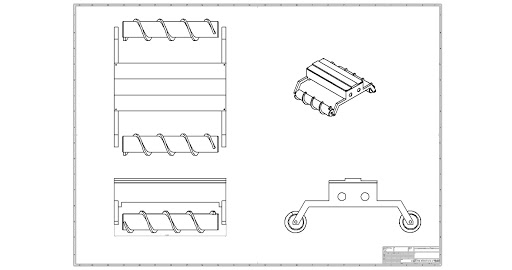
Figure 10: First concept design of ScrewDriver
Figure 11 shows an updated version of figure 10 but it still shared the same problems. Those problems were not realized until proper testing was done on the rapid prototype.
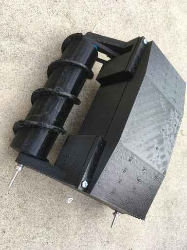
Figure 11: First prototype of the ScrewDriver
Figure 12 shows the final 3D model which fixes all those problems with the previous iterations. The design here has went through many changes while discussing the features with the customer.
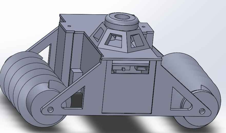
Figure 12: Final design 3D model
System Design / Final Design and Results
Details about the evolution of the design over the semester can be found here.
System Block Diagram
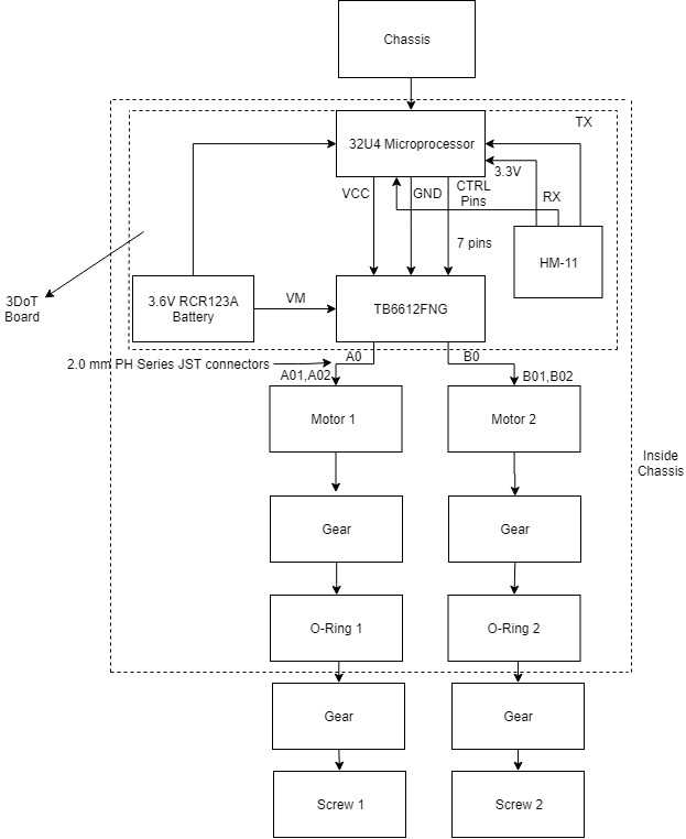
Figure 13: The system block diagram for the ScrewDriver is illustrated. An overview of the interfaces and subsystems is represented in this diagram.
The block diagram shown describes how the components in the 3DoT board interface with the DC motors and how the mechanical components interact with the motors. The 3DoT board is shown in detail where the processor used is the ATmega 32U4 and it is powered by a 3.6V RCR123A battery. The processor interfaces with the HM-11 through the RX and TX pins and the serial port of the 32U4. The TB6612FNG motor driver is controlled through 7 control pins: AIN1, AIN2, BIN1, BIN2, STBY, PWMA, PWMB. These pins determine the speed and direction of the motors. The PWM pins will control the percent duty cycle the motors will receive from the Vm pin. The motors are then connected to the 3DoT board using 2.0mm PH Series JST connectors. Finally, the motors have gears on them which will transfer the power to the screws using o-rings and another set of gears on the screws themselves.
Interface Definition
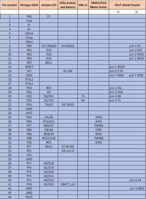
Figure 14:Interface Matrix for the 3DoT board inside the ScrewDriver
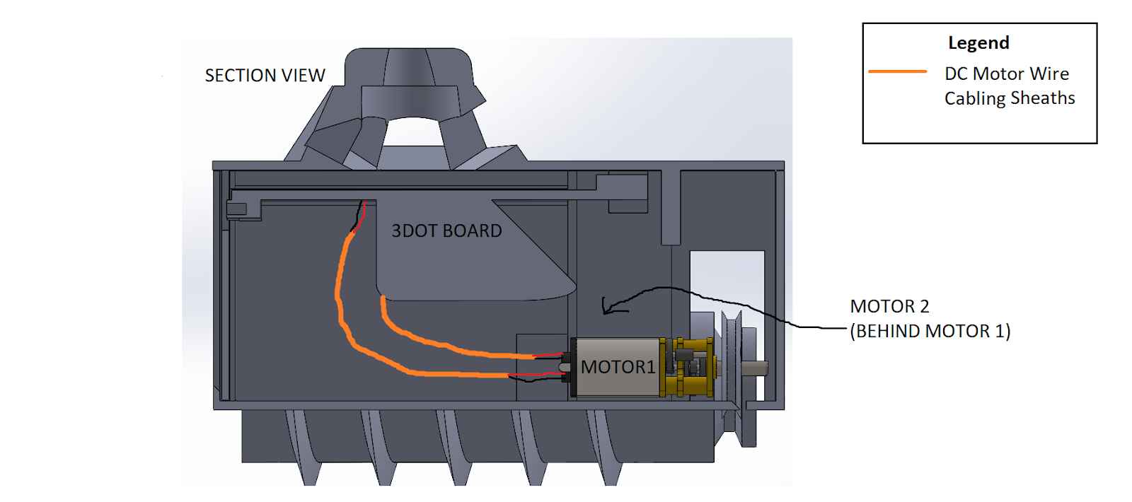
Figure 15: Cable tree for the 3DoT ScrewDriver
The cable tree is shown above and since only the 3DoT board will be used, the only wires running through the chassis are the power lines for the DC motors. The lines will run as shown and the connectors to the 3DoT board are keyed 2.0 mm PH Series JST connectors.
Modeling/Experimental Results
| Model | Status |
| Breadboard Experiments | Complete |
| Current Draw Tests | Complete |
| Battery Life Calculation | Complete |
| Rapid Prototype Speed Tests | Complete |
| Speed and Torque Calculations | Complete |
| Physics of Screw Propulsion Study | Complete |
| Trade-off studies | Complete |
| Rapid Prototype Obstacle Tests | Complete |
| Final Robot Speed Tests | Complete |
| Final Robot Obstacle Tests | Complete |
The links to the completed models are shown below.
For modeling, many experiments were carried. Some of them were theoretical back of the envelope calculations, and others were full-scale prototype experiments. The list of all the models executed is shown below:
Rapid prototype and final speed and obstacle tests
Current draw tests and battery life calculation
This post has speed and torque calculations, physics of screw propulsion and the evolution of the mechanical design.
Mission Command and Control
3DoT Robots
| Hardware | Software |
| Personal Computer | Arxterra Control Panel |
| Smartphone | ArxRobot App |
| 3DoT Board | Arduino and Robot3DoT Library |
The figure shows an overview of how the 3DoT board will communicate with the ArxRobot App. It uses the HM-11 Bluetooth module to send and receive commands and the motors will move accordingly. The code used for the ScrewDriver is the ArxRobot_Basic sketch which contains all the move commands we need to control the robot.
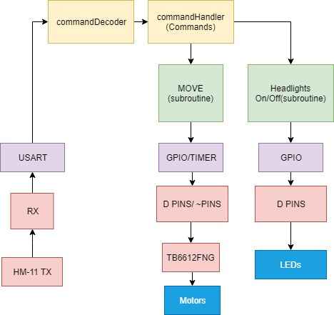
Figure 16:The software block diagram is shown. The process of receiving and decode a Bluetooth command to move the motors is illustrated.
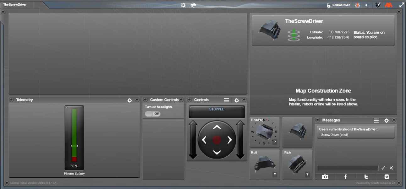
Figure 17: Shown here is the Arxterra Control Panel customized for the ScrewDriver. The custom avatar is shown and a concept for a future custom command “Turn on headlights” is shown as well.
Electronic Design
The ScrewDriver does not contain any sensors at this point, so the only electronic components required were the ones used to create the prototype being: the TB6612FNG motor driver, Arduino Leonardo, 9V DC motor, HM-11 Bluetooth module and a 9V battery. These components were used to mimic the 3DoT board. In the final model, the 3DoT board is used along with 6V DC motors.
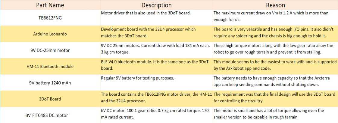
Figure 18: The electronic component name, description and reason for usage is listed for every single component used throughout the implementation of the ScrewDriver.
PCB Design
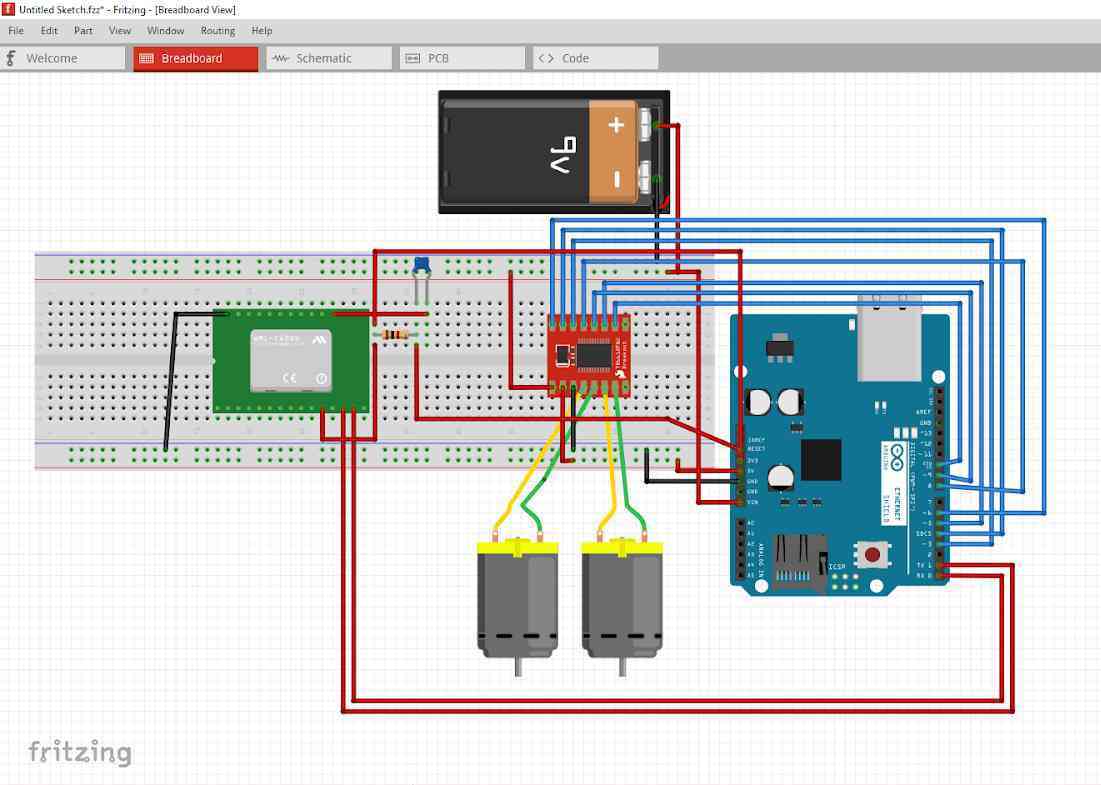
Figure 19: Fritzing diagram for the circuit used in the ScrewDriver prototype.
The circuit shown above was built and place inside the ScrewDriver prototype chassis to control it for testing and rapid prototyping purposes.
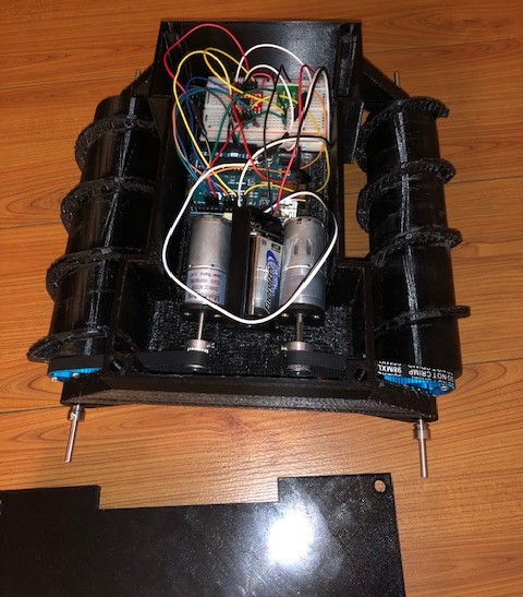
Figure 20: The breadboard circuit is shown with all the electrical components mounted within the chassis.
The figure above shows how the circuit was built and mounted inside the prototype chassis. The Arduino Leonardo is visible in the middle of the chassis with the breadboard above it. The breadboard has the TB6612FNG motor driver on it and the HM-11 Bluetooth module.
The ScrewDriver does not require a PCB as of this generation, but is possible for future generations to implement more functionalities such as headlights, sensors and servos.
Firmware
The testing code used to control the motor speed and direction can be found here under software. The main software used to control both the prototype and the final robot is the ArxRobot_Basic.ino sketch which contains all the code required to move using the ArxRobot app and the Arxterra control panel. No custom commands were required for this project.
Mechanical/Hardware Design
All the details about the mechanical design can be found in here.
Verification & Validation Test Plan
| Requirement Number | Requirement Text | Verification Success Criteria | Verification Method | Test Case where Requirement is Tested |
| L 1.1 | The robot will have two independent propelling screws. | The screws are able to rotate freely from the chassis | Inspection | TC-1 |
| L 1.2 | The robot’s chassis and screws will be 3D modelled and printed. | The material is verified in the SolidWorks model. | Inspection | TC-1 |
| L 1.3 | The robot shall be able to drive through the course without a large amount of dirt getting stuck between the threads of the screws. | The screws aren’t clogged by stuck soil or sand. The amount stuck does not exceed half the height of the threads. | Test | TC-3 |
| L 1.4 | The robot shall be able traverse over soil, small branches and twigs present in the course defined in the mission profile. | The robot shall not be stuck in soil or any of the mentioned elements in the course. | Demonstration | TC-3 |
| L 1.5 | The robot should be able to traverse over obstacles up to 0.25 inch in diameter found in the course. | The obstacle used to test is at least .25 inches in diameter. The robot is able to traverse over the obstacle. | Test | TC-3 |
| L 1.6 | The robot shall be stable enough to exceed an elevation angle of 55 degrees from the ground when traversing through the course. | The robot does not exceed an elevation angle of 55 degrees from the ground when going over obstacles. | Demonstration | TC-3 |
| L 1.7 | The robot shall be able to turn in place. | The robot shall demonstrate the ability to turn in place. | Demonstration | TC-2 |
| L 1.8 | The robot shall be able to move parallel to the axis of rotation on loose surfaces such as sand. | Two test criteria:
The robot can move forward (½) The robot can move backward (½) |
Test | TC-2 |
| L 1.9 | The robot shall be able to move perpendicular to the axis of rotation. | Two test criteria:
The robot can move left (½) The robot can move right (½) |
Test | TC-2 |
| L 1.10 | The robot shall be able to communicate with the operator’s Bluetooth device via the Arxterra app. | The robot can be controlled by the Arxterra app | Test | TC-2 |
| L 1.11 | The robot shall go through the course described in the mission profile. | The robot is tested at the course near the traffic circle at CSULB | Demonstration | TC-3 |
| L 1.12 | The screws will be driven by DC motors. | The driving motors are inside the chassis | Inspection | TC-1 |
| L 1.13 | The robot’s controlling circuitry will be contained in the chassis. | The electronics and motors are located inside the chassis | Inspection | TC-1 |
| L 1.14 | Project shall be safe to operate, as determined by the CSULB COE Health and Safety Policy. | The robot doesn’t break any safety policies defined in the constraints section | Inspection | TC-1 |
| L 1.15 | The robot will use the 3DoT board for controlling the motors. | The robot chassis contains the 3DoT board as the main control unit. | Inspection | TC-1 |
| L 2.1.1 | The final robot will have two screws of the length of 3.42 inches and diameter 1.5 inches | The robot has two screws, the length of each screw is 5 inches, the diameter of the screw is 1 inch | Test | TC-1 |
| L 2.1.2 | The screws will be printed with oppositely threaded notches. | The screws are printed with oppositely threaded notches | Inspection | TC-1 |
| L 2.2.1 | The 3-3-3 rule shall be followed when printing the screws unless printed at the library. | The print is shown in 1 file | Inspection | TC-1 |
| L 2.2.2 | The 3-3-3 rule shall be followed when printing the chassis unless printed at the library. | The print is shown in 1 file | Inspection | TC-1 |
| L 2.2.3 | The screws and chassis will be 3D printed out of ABS plastic | The chassis and screws are printed out of ABS | Inspection | TC-1 |
| L 2.3.1 | The screws will have a large enough pitch of 0.5 inches between the threads making it difficult for soil to be trapped between notches. | The amount of soil/sand stuck does not exceed half the height of the threads. | Inspection | TC-3 |
| L 2.4.1 | The DC motors will have a rated torque of 0.7 kg.cm to provide enough torque for the screws to traverse over various obstacles on the course. | The DC motors have a rated torque of 0.7 kg.cm | Inspection | TC-1 |
| L 2.4.2 | The gear ratio from the motors to the screws shall be 1:1 to prevent any speed loss. | The gear ratio between the motors to the screws is 1:1 | Test | TC-1 |
| L 2.5.1 | The diameter of the screws will be 1.5 inches allowing it to go over smaller objects. | The diameter of the screws is 1 inch | Test | TC-1 |
| L 2.6.1 | The distance between the screws will be 2.85 inches giving it a wide base. | There are two inches between the screws | Test | TC-1 |
| L 2.6.2 | The center of mass of the robot shall be located near the bottom since the screws and motors are near the bottom. | The center of mass of the robot is located at the bottom of the robot | Test | TC-1 |
| L 2.10.1 | The Bluetooth commands shall be received via the HM-11 Bluetooth module. | The Arxterra app receives commands from the Hm-11 | Test | TC-2 |
| L 2.11.1 | The robot shall be tested on a predefined course on campus containing branches, soil, and twigs. | The robot is tested at the course near the traffic circle at CSULB | Demonstration | TC-3 |
| L 2.12.1 | The motors for the final robot will be DC 6V 155 RPM 100:1. | The motors are DC 6V 155 RPM 100:1 | Inspection | TC-1 |
| L 2.12.2 | The robot’s motors will be driven by the TB6612FNG motor driver. | The TB6612FNG motor driver is present | Inspection | TC-1 |
| L 2.13.1 | The robot will be driven by motors small enough to fit in the chassis. | The chassis will contain both motors along with the 3DoT board | Inspection | TC-1 |
TC-1 Disassembly/Reassembly:
This test case starts at disassembling the robot. As the robot is being disassembled all inspection type requirements will be verified. The requirements for this test were grouped together because they can call be observed through the disassembly of the robot.
TC-2 Operation:
This test case tests the basic operation of the ScrewDriver and the control of the Arxterra App. It demonstrates that on an ideal surface the ScrewDriver can move forward,backwards, left and right while controlled by the Arxterra app.
TC-3 Traveling on the Course: The robot shall traverse a course around the traffic circle at CSULB as defined in the mission profile. This course will include traveling over grass, dirt, twigs, and will finish by attempting to travel over different size obstacles. After the course is completed the durability of the robot will be checked to make sure that it doesn’t have any debris inside of it.
Concluding Thoughts and Future Work
Concerning manufacturing and design, we are aware that a number of aesthetic improvements can be made to the SolidWorks 3D model. In the interest of time, however, creative additions were kept to a minimum and the 3D model was made largely utilitarian to allow it to fulfill the mission profile. Perhaps inspiration can be taken elsewhere to produce a more appealing looking robot. And concerning the electronics and mechanical aspects, perhaps future teams can try out a different motor drive system instead of the belt and pulley system that we utilized.
References/Resources
These are the starting resource files for the next generation of robots. All documentation shall be uploaded, linked to, and archived in to the Arxterra Google Drive. The “Resource” section includes links to the following material.
- Project Video
- CDR
- PDR
- Project Libre
- Verification and Validation Plan
- Solidworks Files (Chassis, Screws)
- Fritzing File
- Bill of Materials