6 Wheel Electronic Differential
By: Jordan Smallwood (Project Manager and Electronics & Control)
Approved By: Miguel Garcia (Quality Assurance)
Table of Contents
Introduction
Have you ever considered how a train makes a turn? Really try and think about it, it has two wheels on a track separated by a distance but when it turns it doesn’t fly off the track. It’s not very intuitive but if a train was making a right turn, going along a curve to the right, the left wheel is traveling a greater distance since it’s on the outer curve. However, the two wheels traveling along the track are joined by a steel shaft that doesn’t break. So, what is the explanation for this phenomenon?
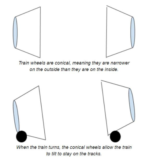
Figure 1: Differential Explanation
Trains have conical wheels that allow for this freedom of motion at the track, they slide back and forth along the track allowing the train to tilt one way or the other. Now, the Pathfinder is not a train and will not be riding along tracks, but the same concept applies.
Encoders
The Pathfinder has 6 motors all connected to the same power source and in a perfect world if we supplied each of these motors with the same PWM command they would all go the same speed. However, this is not a perfect world and many factors can come into play when it comes to how fast the motor spins. First off, the whole premise behind the Pathfinder is that it can climb objects asymmetrically, that is each motor can be experiencing a different load which is one of the major reasons behind needing an electronic differential. Secondly, when we make turns we want to make sure the wheels are going at the speed we want them to account for the difference in distance traveled. And finally, due to natural mismatch in motor build we need to examine the difference in speed of the motors.
Herein lies the problem we have faced and have tried to come up with a solution for the past month or so. The motors on the Pathfinder currently do not have any encoders. We have looked at every possible type of encoder such as magnetic, optical, and any other possible type but we have finally realized that the only way of getting a truly good output from the encoder is by purchasing motors that already have encoders installed. The reason behind this is simply to achieve the greatest possible resolution with your encoders is to get your output prior to the gearbox. I can not stress that enough. If you ever have a project that you need encoders on make sure you either buy motors with an extended shaft or motors that have encoders included otherwise you might find yourself in the same situation. $200 later we now have our encoders.
Hall Effect Sensors
Now that we have motors with encoders connected prior to the gear-box we need to understand how they work.
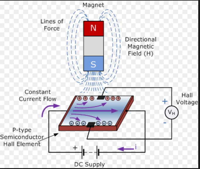
Figure 2: Diagram of Hall Effect Sensor
In the presence of a changing magnetic field, a charged semiconductor plate will deflect the flow of electrons from one side or the other. Consequently, one side of the plate will become more negative while the other becomes more positive. This is the basic principle of how a hall effect sensor works. A magnet is placed perpendicularly to the sensor plate and the Hall Voltage on the plate is observed. This is typically found in many encoding applications. There are two different types of Hall Effect sensors available, one that is a measure of flux density and the other is compared against some threshold voltage. We will be utilizing the latter since we are only concerned with the count and not the distance to the magnet. Another great feature of hall-effect sensors is their ability to toggle between states which means that bouncing is not an issue.
The encoders that we have paired with our motors have 6 pins associated with them, they are as follows:
- M1 (Motor Power Supply 1)
- GND (Encoder Ground)
- C1 (Encoder Channel 1)
- C2 (Encoder Channel 2)
- VCC (Encoder VCC)
- M2 (Motor Power Supply 1)
For each revolution of the motor we will receive 11 counts per channel which results in 22 CPR overall. Depending on the gear-box reduction ratio, which in our case is 280 (14 RPM), we can calculate the resolution as follows:
Figure 3: Determining the Resolution of Shaft Encoders
Note that this is the maximum resolution and there is an included error from the motor manufacturers data sheet. Depending on the amount of precision you need you can always use both channels, also if you need to determine direction of the motors then you will need to use both channels. For our purposes though we will only need to occupy one channel since pin allocation has become something of an issue for us.
Implementation
To accurately and efficiently read the encoders we will be using interrupts. By using interrupts we can allow the code to progress as normal and minimize the amount of time outside of the main loop. In order to make this 6 wheel differential work we have two options.
- We can set a desired speed that the robot travels and make all 6 wheels track that speed, or try to stay within a certain margin of that speed.
- We can set one of the motors to a certain PWM value that we are comfortable with and force the other 5 motors to follow that speed.
The issue with the second option is that even though we are sending a constant speed to one motor, it could fluctuate about some speed and that can cause issues with our control scheme. There is much less error when tracking a step input rather than a varying signal. Therefore the plan of action will be to set a desired speed, within capable limits of the motors, and make each motor follow that desired state.
In order to realize this we are going to need to design a controller that can follow this input. In my experience one of the easiest types of controllers to implement would be a proportional controller. Proportional control is relatively simple and comes at a low cost to the memory of our MC.
After running some experiments and playing with the gain we can figure out exactly how to implement this type of controller. For our purposes we will have 6 controllers, one for each of the motors. The input will be a constant velocity and the output from the encoders will be fed back to the summing junction to compare with the set point.
Software
Reading the Encoders
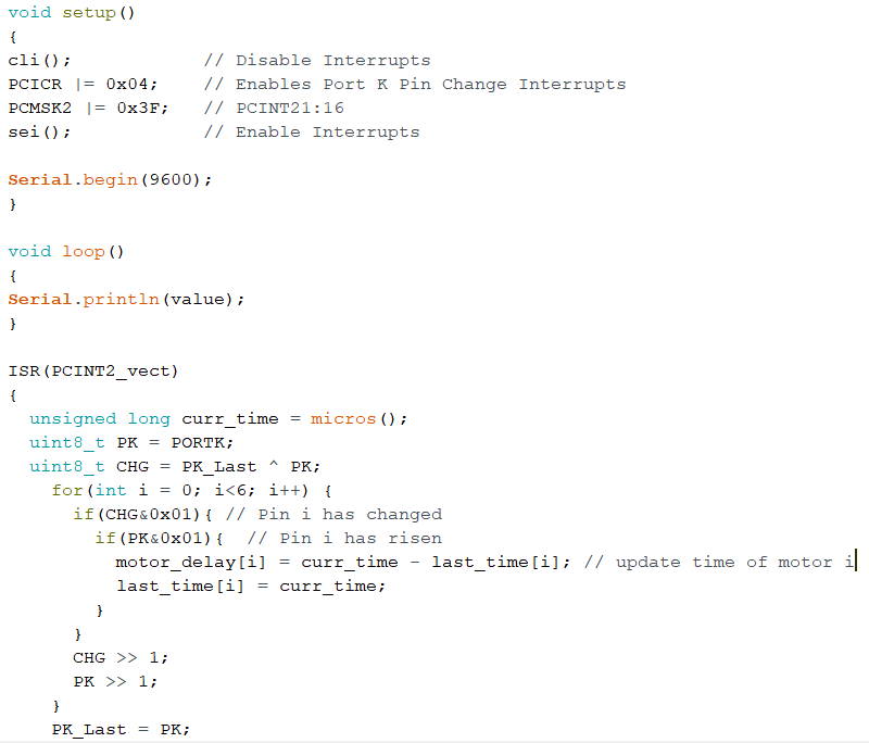
To efficiently read the encoders we will need to set up some interrupt service routines, specifically one for each motors encoder channel. This will be done similar to the following code:
Figure 4: Code for reading the encoders
To get more information on how to set up interrupts like this please refer to the blog post regarding them HERE.
To verify that the output from the ISR was correct I applied a test voltage from a power source and found that the elapsed time between pulses was about 1450 microseconds for the 14RPM motors. After playing with the values and factoring in the gear ratio and CPR values the no-load speed of the 14 RPM motor was approximately 13.4 RPM which verified that these encoders are providing good feedback.
Control
Knowing the limitations of your control is important when it comes to implementing a design. For example, we know that these motors can spin without any load at a maximum of about 14 RPM. So, we want to travel at a speed that will allow for the system to adjust for disturbances such as changing loads, error in sensor readings, and anything else that might present itself. Therefore, we will set the desired speed to a comfortable 10 RPM, this will allow the system to adjust in both directions.
We can include different equations in our ISR to calculate the speed but it would be easier if we just returned the delay between pulses and let the control track that instead. For a speed of 10 RPM it can be shown that the delay is about 1,950 micro seconds. If the actual speed of the motor is greater than 10 RPM then the delay would be less and if the motor was traveling slower the delay would be greater. Also, if we wanted to apply a gain to the controller we would need to come up with something that makes sense. If one of the motors was traveling faster than the set point by 1 RPM then that would translate to about 100 microseconds so if we wanted to allow the controller to respond aggressively to large errors a gain of about 4 would do the trick. With all of that in mind we can construct the controller as follows:
Figure 5: Code for Speed Controller
References
- https://www.arxterra.com/pin-change-interrupts/
- https://thewanderingengineer.com/2014/08/11/arduino-pin-change-interrupts/
- https://www.arduino.cc/en/Tutorial/BlinkWithoutDelay
- https://sciworthy.com/why-trains-dont-fall-off-the-track-when-turning/
- https://www.electronics-tutorials.ws/electromagnetism/hall-effect.html


