By: Tate McGeary
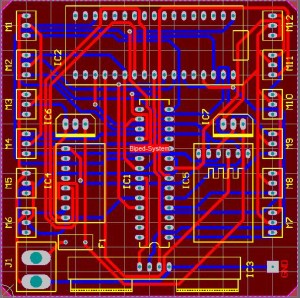
By taking the above Fritzing diagram created by group member in charge of electronics, the group created an interface definition along with a schematic to be used for modeling. With the help of Tony Huynh the group created a PCB schematic to be sent to http://imall.iteadstudio.com/ . The company took about 8 days to process, manufacture, and send the PCB boards, 10 10x10cm PCB boards.
Below is an image of the routing.
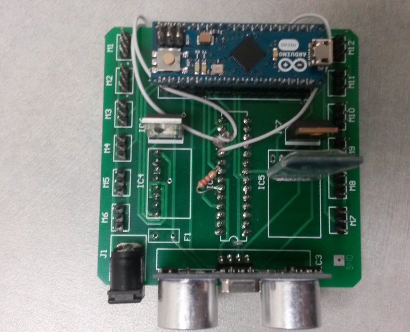
Once received, the group tested each port to ensure the PCB was created according to the design sent to the company. The testing was carried out by using a digital multi-meter set on continuity and each port connection was tested. The PCB was created according to the design specifications sent to the company.
Issues
The issues that occurred were in two fold.
(1) The miss wiring of the TLC5940 to the Arduino Micro. The original fritzing diagram did not take into account how the board was supposed to be wire beyond just wiring to PWM ports.
(2) Lack of pull-up and pull-down resistors. When using the TLC5940 IC, RHB or NT package, there has to be a series of pull-up resistors in order for the IC to work. 1 pull-up resistor to 5V rail for each output and a pull-down resistor to GND at the IREF pin. Without the pull-down the board will not function, and without the pull-up the PWM outputs do not have enough of an amplitude to drive a servo. All resistors need to be 2.2k Ohm
Resolving the Issues
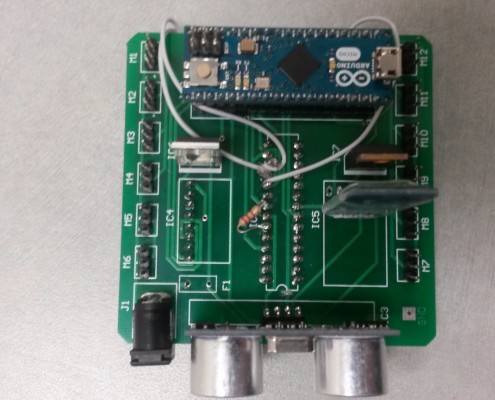
(1) In order to fix the miss wiring of the TLC5940 the group had to break the connections that were wired wrong on the TLC5940. To break the connections the routes were just cut clean through to deactivate that connection. To re-wire the board, Teflon wires were used to connect the correct pins to each other.
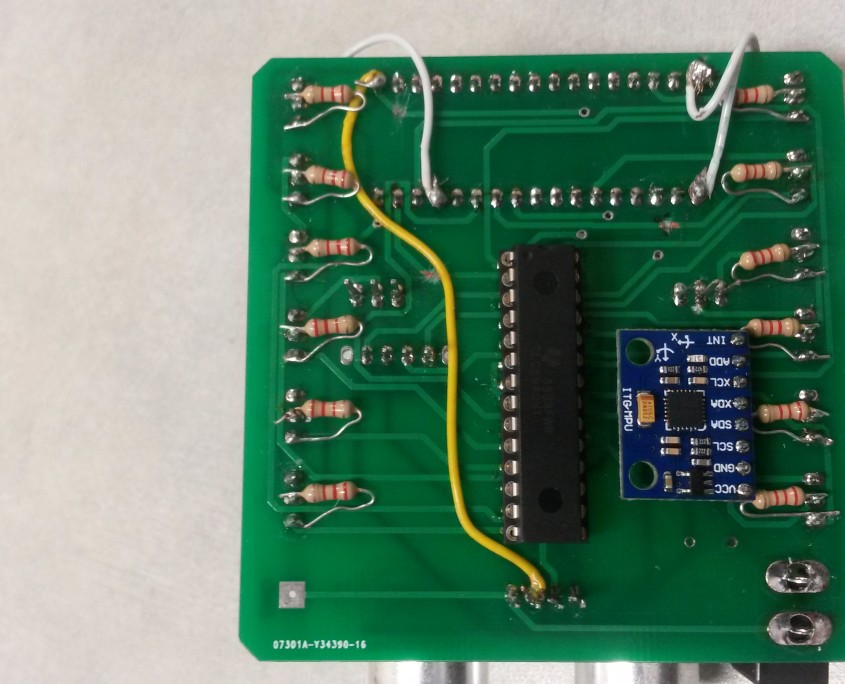
(2) To fix the lack of resistors, the group soldered in the necessary resistors at the correct locations in order to compensate for the oversight.
After each break and solder the group check every pin to ensure there was no shorts or over-lap that could cause the function of the board to go haywire. So far every break worked.
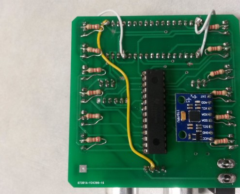
Once fixed the board looked like the following:
After the breaks where made, the board was then uploaded with a code to move a servo +/- 180 degrees to ensure proper wiring. Immediately it became apparent that there was an issue, the servo would move 180 degrees and jitter. The other issue that occurred was when all 12 servos were attached, each one would go haywire. This means that there is not enough power being delivered to the circuit. Primarily the current could be too low, as the voltage has been checked and it is at the rated 5V.
The problem could be caused by one of three issues:
(1) A thermal breakdown in the voltage regulator
-To check if it is a thermal breakdown in the voltage regulator, a heat-sink will be applied with thermal paste. If the outcome remains the same then issue is most likely due to the second issue.
(2) The voltage regulator MC7805CT is not delivering enough current.
– To fix this, the group will use a LM323T which will be installed on the board. It has a 5V 3A output compared to a 5V 1A output the MC7805CT has.
(3) The breaks on the board were not clean enough, and the new wiring is not correct
-To check this the board will be checked
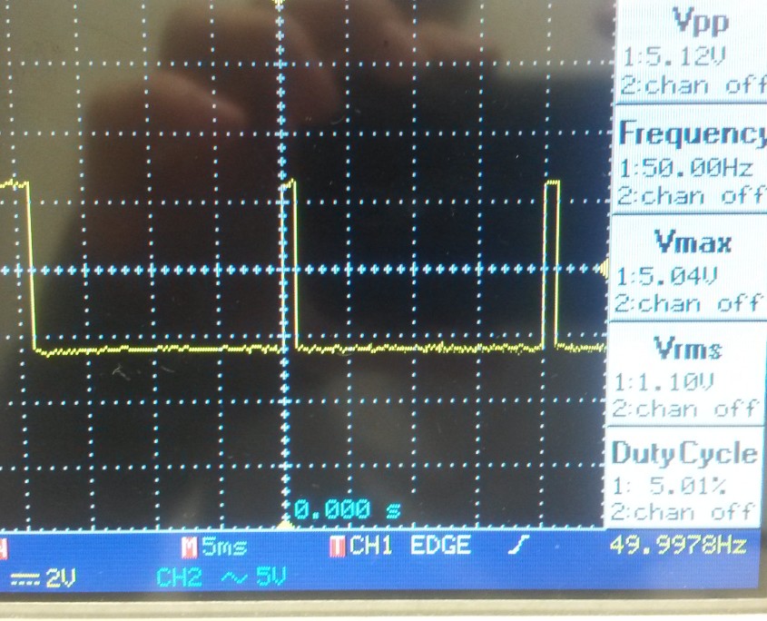
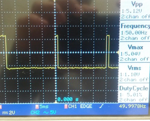
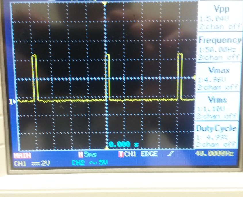
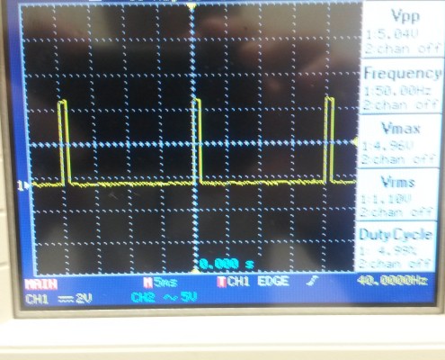
-The group hooked up the PCB board to an oscilloscope the check if the correct pulses. When comparing the PCB output with the breadboard’s output the group found no difference, as such it is believed that it is not a wiring issue. (See picture below)
Future Plans:
When time allows, it is planned to remake the PCB. The goal is make the PCB smaller then its current dimensions of 3″ x 3″. To do this the plan is to switch as many of the components to surface mount as possible. The TLC5940 would go from the NT package; which is a through hole design; to a PWP package. The resistors would be switched to 1206 resistors, 3.2 mm x 1.6 mm, the HC-06 would be mounted without its shield directly to the board, surface mount reset able fuses would be assigned to the power inputs of the servos and 1 fast blow fuse would be used to protect the components. Even the voltage regulators would be switched to surface mount in order to reduce foot print size.

