Fall 2015 MicroBiPed System Schematic
EAGLE SCHEMATIC
By Brian Walton (Controls Engineer)
Approved by Paul Oo (Project Manager)
Approved by Railly Mateo (Systems Engineer)
Introduction to Eagle:
Using EAGLE as a tool to build your schematic for all your subsystems offers multiple advantages:
1) Easy to use set-up aides with ease of schematic building
2) A large number of electronic companies support EAGLE and as such they provide libraries to add to your already existing EAGLE libraries to allow the use of their parts in the EAGLE software.
3) EAGLE comes with a built in PCB (Printed Circuit Board) software to easily go from the schematic to designing the PCB.
a) The available libraries allow using different size components as well as through-hole and surface-mounted components to add to the customization of the PCB to fit size and functionality requirements of the project at hand.
4) Building a schematic through EAGLE shows exactly what components are required for assembling the PCB allowing easy creation of a BoM (Bill of Materials) to simplify in the ordering of materials.
Our Eagle Schematic:
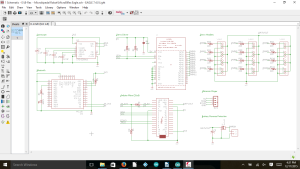
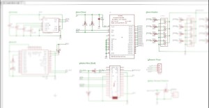
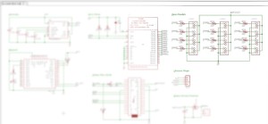
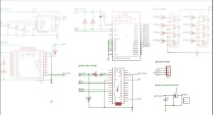
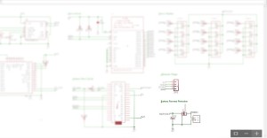
The full schematic can be downloaded from here: Eagle Schematic.
Project μBiped, also known as Project BiRex and Project Little Foot, required the use of a servo driver, Arduino Micro, Ultrasonic, Gyroscope, Bluetooth, and Battery Reverse Protection.
Figure 2 focuses on the gyroscope from the overall schematic. It was decided to place the IC (integrated circuit) for the gyroscope directly to the PCB instead of using through-hole pins for the component itself. As a result extra capacitors had to be added to maintain the functionality of the gyroscoope.
Figure 3 focuses on the Bluetooth from the overall schematic. The HC-06 was placed directly onto the PCB to allow wireless communication with the Arxterra application on a phone. The layout chosen for the schematic dictated the use of a HC-06 without a backboard.
Figure 4 focuses on the servo driver from the overall schematic. The servo driver IC was also laid directly onto the PCB, requiring extra resistors and a capacitor to maintain functionality. In conjunction with the servo driver, figure 5 shows the components needed to use the driver. It was required to have headers to be able to attach the servos to the PCB. Resistors were added onto the signal lines. The servo driver allowed the use of up to 16 servos which was quite a bit more than the 6 required for the project. The size requirement for the PCB allowed extra servo headers to be added to the design so the PCB allows for the use for up to 12 servos.
Figure 6 focuses on the Arduino Arduino and Ultrasonic Sensor from the overall schematic. The Arduino Micro and Ultrasonic were placed directly onto the PCB.
FIgure 7 focuses on the battery from the overall schematic. Battery Reverse Protection was added for added safety of components. The value of the capacitor used (1000 μF) was chosen based off of the number of servos used.
Notes:
Once the schematic is designed it is useful to label all connections and organize the schematic to aide in PCB design.
A copy of EAGLE can be downloaded here:
http://www.cadsoftusa.com/download-eagle/

