Goliath Fall 2017
Final Blog Post
Mark Huffman (Project Manager)
Introduction
By Mark Huffman (Project Manager)
The purpose of this document is to provide final closure for Goliath Fall 2017 Project. Overall, this document will provide useful linkage to all aspects of the project. It is recommended to use the table of contents to jump to sections as needed.
Project Members:
Mark Huffman (Project Manager)
Vanessa Enriquez (Manufacturing Engineer)
John Ocampo (Electronics and Controls Engineer)
Nornubari Kanabolo (Missions and Systems Engineer)
Executive Summary
By Mark Huffman (Project Manager)
Mission Objective
The goal of this project was to improve on 302 Goliath tank design from the Fall 2016 Class and adapt to a completely different mission goal. The mission was to navigate a 2D paper/cloth maze under remote control and then have the Goliath repeat the route autonomously. For an added challenge an extra version was added that where all bots must navigate the maze autonomously without running into each other. As a backup option, the bots should be able to navigate a single path out of the maze.
Key Features
Color Sensors for Line Tracking
The use of color sensors allows the goliath to follow lines on any type of maze material (as long as the values are calibrated).
LED Grid Display
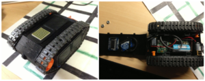
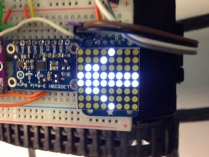
Used to display next turn direction, indicating if a turn action is needed and if an object is detected in the Goliath’s path.
Smaller 3Dot Body with Access
The bodywork was redesigned to fit the 3Dot board more tightly and provide access to necessary ports for programming/charging.
Complete Axterra App Control
The mode, movement control, obstacle avoidance and maze control is all controllable from the Axterra App.
Ability to navigate a 2D maze under RC and Autonomously
Using combined software and Axterra control, the Goliath can navigate the maze internally and physically
Project Requirements
By Mark Huffman (Project Manager)
Level 1 Requirements
1. Project Schedule – Project shall be ready by Wednesday, December 13th, 2017
2. Operational Task – The Goliath will have the functionality to be connected remotely using Arxterra
3. Toy – Elements – The Goliath will behave like a toy
4. Driving Surface – The Goliath will be able to drive on flat surfaces
5. Driving Surface – The Goliath shall traverse on cloth, paper and linoleum
6. Print Time – All modifications shall allow the Goliath to be printed under a total print time of 6 hours with no part taking longer than 2 hours
7. 3Dot – The Goliath will use the 3Dot Board
8. Appearance – The Goliath should appear in scale to the real Goliath 302 tank
9. Operation Task – The Goliath should be told to move remotely using Arxterra
10. Budget – The total cost of the Goliath shall remain under $350
11. Operation Task – The Goliath should traverse a maze under remote control
12. Operation Task – The Goliath should traverse the maze without user input
13. Operational Task – The Goliath should remember the manual instructions given, in terms of navigating the maze
14. Creative – The Goliath should display the next turn direction on LED grid display
15. Creative – The Goliath should have easy access for charging and programming hookup
16. Duration – The Goliath shall remain operating for at least an hour
17. Creative – The Goliath should be smaller than the final design of the previous version
18. Assembly – All of the Goliath electronics and motors should be disassemble and reassemble within 20 minutes
19. Avoidance – The Goliath should detect and avoid running into other bots on the maze
Level 2 Requirements
1. Weight – Mass of Goliath should not exceed 350 grams
2. Power Limits – Voltage drawn from the 3DOT must not exceed 3.6V
3. Visible Range – Goliath should detect objects in an 8-inch radius
4. Durability – Goliath should withstand impact of wall and other robots
5. Current draw limit – Total current drawn from the 3DOT must not exceed 650mAh
6. Turn indicator – 8×8 LED display shall be placed on top of Goliath
7. Cable routing – The wires in Goliath should be clean so no interference during disassembly
8. Maze tracking – Goliath should be able to keep track and identify its location on the maze internally
9. Overall Size – The Goliath will be smaller than 4.71x 3.77 x 1.8 inches (Current size)
Level 2 Sub-Electronic Requirements
1. LED Matrix – Power – The Goliath’s LED Matrix shall consume 3.3[V] and 1 [mA] for operation
2. IR Sensor – Power – The Goliath’s IR sensor shall not use consume more than 3.3[V] and 4.4 [mA]
3. Gyroscope-Power – The Goliath’s Gyroscope shall not use consume more than 3.6[V] and 3.2 [mA]
4. LED Matrix-Turning – A LED Matrix shall be utilized displaying the direction of the Goliath’s next move
5. Color Sensor- Tracking – The Goliath should utilize 2 color sensors(TCS34725) to follow the lines of the maze. With an optimal range of 10[mm]
6. Gyroscope-Tracking – The Goliath shall utilize a gyroscope to make turns within the maze
7. IR Sensor – Range – The Goliath shall utilize an IR Sensor to detect objects
Level 2 Sub-Manufacturing Requirements
1. Goliath-Size Change – The Goliath shall measure 4.71×3.3×1.8 (LxWxH)
2. Wire Routing – Wires should be maintained on a clear path (away from the center)by adding loops to the inside of the side panels (where possible).
3. Durability – At max acceleration, force shall not exceed F<<350*a
4. Appearance – The added LED display shall lay flush to the top panel surface to maintain goliath structure
5. Component placement – Mass of Goliath will be evenly distributed (front to back)
6. Component placement – The goliath shall have two gears (front and back) in opposite directions
System Design
Nornubari Kanabolo (Missions and Systems Engineer)
System Block Diagram
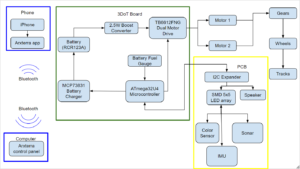
System block diagrams illustrate how each component of the Goliath communicates and connects with each other. With the new 3DoT board there is no need to obtain a Bluetooth module since it has a built-in Bluetooth transceiver. A rechargeable battery is also built into the board, which powers all components connected to it.
System Resource Reports
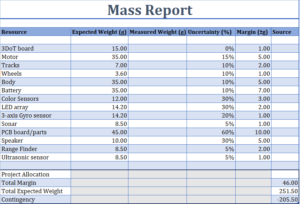
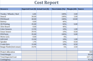
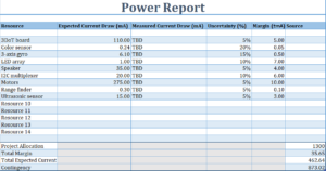
These tables represnt the resource reports for the Goliath. These are included along with some others in the Preliminary Project Plan (PPP).
Under the advisement of Professor Hill, a general power usage chart for the 3Dot was developed. This version incorporates all the sensors used in the Goliath final design and represents the overall voltage, current and power needs of the Goliath.
Manufacturing Design
Vanessa Enriquez (Manufacturing Engineer)
Initial Design
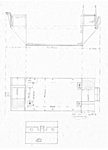
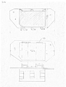
Starting with the previous semester’s final design, new sketches were created. The main new design was the relocation of the motors. Have one in the back and another in the front. This allowed the horizontal dimension to shrink to fit the 3Dot board snugly.
Design Iterations
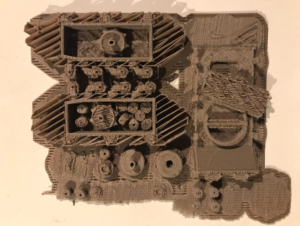
Along the way we went through a few design iterations. Each improving or correcting errors in measurements or design features. Part of the challenge was just getting the body to print correctly and accurately.
PCB Design
The custom printed circuit board was designed to include both the gyro sensor and the LED display on the top panel. This was the desired simplification, as top panel space was limited and the breakout boards contained extra circuity that was unneeded. Combining these boards proved challenging however as we were unable to complete this task in time.
Final Design
The final design, fixed much of our support and print issues. Mainly with the support for the motors being strong enough to hold them in place. Along with this IO and mounting holes were placed more accurately and allowed for final assembly. Although still not perfect, the design can be iterated to improve the overall rigidity.
Through the process print issues where discovered. These issues held up the assembly timeline but, overall a lot was learned.
Experiments
John Ocampo (Electronics and Controls Engineer)
Component Testing
Before using any sensors in the final design, they must be tested for usability. Part of this testing was discovering how to use the components, their power requirements and software requirements.
Gyro Testing and Usage
For the usage of the gyro, the power requirements were needed. A second test involving degree accuracy along the different axises would have been useful.
Software
By Mark Huffman (Project Manager)
Line Following
In order to follow the maze lines with color sensors, a generic version of line following was developed for use by all other projects. The generic code is presented here along with a detailed explanation of its install and use.
LED Display
The LED display is capable of drawing lines, shapes and even text. For our purposes, most of this was stripped away allowing shapes to be used to define particular actions. This post contains the explanations for how the code functions and what the LED symbols actually mean.
Virtual Maze Navigation (EE 444 Translation)
The majority of the maze code for this class had already been defined by EE 444. The process of combining this code into this class was the task of Goliath and ModWheels. Combined this code keeps track where any bot is within a maze by keeping track of the location virtually using an internal mapping of the maze. With this combined code navigation across the maze is easily possible.
App Directed RC
In order to complete the main goal of this mission, app directed control to the Goliath was needed. This comprehensive guide talks about how setting up custom commands all the way down to how the major whichway decision making within the maze is effected. This guide defines the general case used by all bots, but the code represented is the Goliath version.
Robot Detection
Using our IR proximity sensor, the code was written to take readings periodically and determine if an object is within three maze squares of the Goliath. The code presented here is able to determine when an object is within range of the sensor. When combined with the rest of the Goliath code, this is used to trigger an object detection recovery action. The recovery plan still needs to be improved along with the detection method, as objects that are “behind” maze walls are currently still visible.
Final Code & Calibration
Combined is the final Goliath code and the files needed to update the 3Dot library. Included is a guide to install on how to install the code an what libraries are needed. Importantly this guide explains the overall code structure and general flow format. Lastly, it is explained how to calibrate the code for a particular chassis and maze material.
Verification Plan
Nornubari Kanabolo (Missions and Systems Engineer)
The testing and verification procedure as defined by the MST is provided here. The internal link to Verification and Validation document is the more useful link as it demonstrates how requirements were passed or meet.
Goliath Setup and User Guide
By Mark Huffman (Project Manager)
This section provides linkage to the Goliath User and control guide. This guide provides user setup in order to use the Goliath as finished by this project. The guide steps through setting up the App for Goliath control and telemetry as well as how to operate Goliath. Useful for demonstrating how everything works together. This would be the best place to start to understand the big picture.
Project Documention
By Mark Huffman (Project Manager)
This section provides linkage to all important documents related to this Goliath Project.
Project Manager Resources
Project Schedule: https://drive.google.com/open?id=1jZuyUCtJ97prDbiMrG2Rd2nzIN7PLl9x
Project Burndown: https://drive.google.com/open?id=1gJRYxyDWI2q93PaB-qHziDULFa9pBdOR
Creative Solutions: https://drive.google.com/open?id=1cClo0uy5VxqpVH9-CAEVvi-kJCVX02BQiuEfgjGqV5g
Project Budget: https://drive.google.com/open?id=1lK4HKJfOgyuRqM6g7a4k4xeRFpjzGBn18eFv7prc6wE
Goliath PDR: https://drive.google.com/open?id=1waecUbvhQsJKl1k6hWB7cwXN2EnhZ_emUpf-R-9VJqU
Project Requirments: https://drive.google.com/open?id=1XXgVytkz0joUKClY3wSbNw-GRu_jOPGCe5jpQChymC0
Important Links: https://drive.google.com/open?id=1f96Aix3jG6tT-4sLTS7qk7W9LzS57CaaHCaOcW0NMCE
Weekly Meetings: https://drive.google.com/open?id=0Byjh7PnLWpiJeTdSVGJrNHFXams
E & C Resources
PCB Parts Breakdown: https://drive.google.com/open?id=12qSjqodhTI7ujAy3a9POoDsDeZB36E1pCmVriK-q1OQ
Fritzing Diagrams: https://drive.google.com/open?id=0Bwc2ek6XC1GbYnY2MEJTMlJ5aGs
System Block Diagram: https://drive.google.com/open?id=0Bwc2ek6XC1Gbb18zY19FZ0hsS1k
Final Goliath Arduino Code: https://drive.google.com/open?id=1bqejv8amimIBqPunKr1n1aHZ_CvA9UFS
Manufacturing Resources
Final Solidworks Model: https://drive.google.com/open?id=1Cp0p7jK1qAZpm0c_XODLzaz17mA52Cc5
Final STL Models: https://drive.google.com/open?id=1Ntev1oAs8KArcKzdteSjSGi6A1g4G1Gh
Final PCB Design: https://drive.google.com/open?id=1vwRGfnJTk5pA_Uv6egdu_Z9Ce4roAVUr
MST Resources
Power Budget: https://drive.google.com/open?id=18Nj92xXovVOK6Kxq2X-FVpj6ReNaxf6f
Software Block Diagram: https://drive.google.com/open?id=0B4HBYs06ml86ZUo2Q2JvQUxzRXM
(Product Breakdown Structure) PBS: https://drive.google.com/open?id=1fnnmksIU4ztakioOvhgZB7gOb5w8WH7HFhyPVkrVVUQ
(Work Breakdown Structure) WBS: https://drive.google.com/open?id=1BvYd-ZnNW_7grhZbdjbOwyTljmoGYTwaftdW_yb3pgY
Interface Matrix: https://drive.google.com/open?id=0B4HBYs06ml86bkJLeW1VTjRKelU
Lessons Learned
By Mark Huffman (Project Manager)
There is so much to learn from this class. At first, everything may seem unrelated but as the class progresses it all begins to all come together. Therefore defining work and the schedule, in the beginning, is very important. The more time you put in along the way the easier the whole project will come together. My key advice would be to follow this order:
- RESEARCH, RESEARCH, RESEARCH. At the start research as much as you can about the past project your building on (start at this document). Then read through all the posts from that semester. Lots of work has already been done and just uncovering it and reading may take time but, it is worth it.
- Get a Prototype working ASAP. Even Hill touches on this point. The main reason is to have time for programming model iterations and so on. Without this, there is no code to write and the code will take the longest!
- Plan to iterate the 3D model at least 5 times. Get a 3D model designed (even if it is rough) and just get it printed. Each time you print it, there will be something to improve or fix that was unthought of. Plus by the time you get to the end the timeline, 3D printing and assembly will be easier.
- Start Coding EARLY. The programming work can be long and tiresome. Most programming takes hours troubleshooting per feature. Starting early gives the highest chance of success. (For reference in EE 444 it took over 10 weeks just to get bots to move on the maze correctly).
- PCB Design has a long Verification time. Designing a PCB is the easy part, getting it approved, then assembled and working is the hard part. (In our class the generic color shields failed to work even though everything had been approved)
- Provide your group with some goal every week. This will help keep your project on task and helps the members remain focused on their independent tasks. Planing this isn’t easy but, as project manager just form a general goal and then ask everyone how to get there.
For our project, we failed to create a custom PCB or fully iterate the 3D model enough times to remove all the issues. But, we did spend enough time on the coding and had a working prototype by week 4. We attempted to pull everything together at the last minute and it did not pay off.
Time will fly in the class by the end. After talking with other classmates it was clear that everyone could have benefited from more time. However, just as in a real company there are deadlines and projects must be completed by a particular date. That is what this class is really for, bring the realness of a work environment into the classroom. This kind of structure can make getting things done sometimes frustrating but, it is just a process to learn. Another useful point in this class in never be afraid to ask hill for help or advice. He may seem intimidating to ask but, he is a very important resource for everything. So, if you don’t know just ask!
Future Improvements
By Mark Huffman (Project Manager)
Our version of Goliath is never really finished. Just as the design or code will never be perfect. Some suggested improvements are listed here.
- Find/Design treads that fit more snugly and prevent slipping.
- Add body access for turning off and on the 3Dot board.
- Reinforce the 3D model so that it holds a more rigid shape (Supports that attach the side panels to the bottom and top panel)
- Add more clearance for the IR proximity sensor.
- Study the effects of using the IR sensor through a tunnel opening.
- Work on obstacle avoidance protocols for different situations in the maze.
- Re-add tank sounds to Goliath.
- Upgrade to the newer 5.03 3Dot board.
- Upgrade the gyro and work on improving Goliath turn accuracy.
There will always be new ways and things to improve, and Goliath will always live on.
Project Video
By Vanessa Enriquez (Manufacturing Engineer) & John Ocampo (Electronics and Controls Engineer)

