Spring 2018 3DoT Hexy: 3D Model (Preliminary/Revisions/Final)
By: Eduardo De La Cruz (Project Manager and Manufacturing Engineer)
Approved by: Miguel Garcia (Quality Assurance)
Table of Contents
Introduction
This blog post contains detailed explanations for the 3D components generated in Solidworks. This post does not contain any dimensions on how to make them in solidworks. If interested in the dimensions of specific parts please see “Spring 2018 3DoT Hexy: Mechanical Drawings” . Our first iteration which is also our preliminary design will be labeled as Update 1: 3DoT Hexy Mk-1 (Prototype). Revisions will be made within this blog post, and will appear under the table of content as “Update n” followed by the date updated.
Related Requirements
Level 1 Requirements
- The robot will be designed to be a toy for people ages 8+.
- In order to minimize manufacturing cost, and packaging cost the robot shall be able to be constructed from subassemblies within 10 minutes.
- The robot shall incorporate 3D printed parts to demonstrate the feasibility of the 3DoT board for 3D printed robots.
- For quick production of the prototype, the preliminary project shall be restricted to six hours of total printing time with a 2 hours limit for each single print.
Level 2 System Requirements
- The robot shall use 3D printed chassis and legs. This follows from the project level requirement about using 3D printed parts.
Update 3: Final 3D Model – Hexy Mk-02 (April 29, 2018)
Chassis
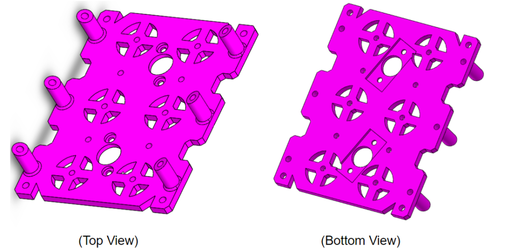
Bottom Plate
Figure 1: Final Bottom Plate Design
Design Changes
- Removed the two wire tubes/wire holes. This was done due to the inability to route all our wires through the two 8 mm holes (which we could not make bigger due to space). As well as, due to the interference of wires with our hardware because we had to place our hardware in the middle of the top panel too. Alternative methods were found to route our wire to the bottom plate below.
- Reduced the width of our bottom plate by 12 mm. Since we removed the wire tubes from our bottom panel we were able to make our cam system fit in a smaller space making our design more compact than before.
- Removed front and back extrusions. These extrusion were removed to provide support for the front sensor enclosure and the rear cable tube, which will be discussed shortly
Top Plate
Figure 2: Final Top Plate Design
Design Changes
- Redesigned extrusions to give easy access to all screw in the bottom plate. In previous revisions of the top plate we saw that not all screws on the bottom plate could be easily reached with a screw driver. Therefore, a solution was to place holes over the screws to eliminate the need of removing the top panel for screw adjustments.
- The area along the middle was configured to the width of the 3DoT board ~35 mm.
- Added more space along the front to provide a mounting point for the sensor enclosure.
- Added decorative fangs to the front to give is the aesthetics of a spider.
Legs
Femurs
Figure 3: Final Femur Design
Design Changes
- Increased size of femur-to-tibia joint to prevent layer splitting in the PLA material.
- Outer femurs, femur-to-tibia joints where re-designed to have an angled offset to provide more stability/balance while walking. The prototype design was having issue stabilizing its weight as it walked. After reviewing methods to solve this issue we found that the previous Spiderbot (3DoT David) had the same issue and solved it by offsetting the femur-to-gear joint in a similar way as shown below. If interested in seeing their solution see “Spring 2016: 3DoT David Design Evolution”. This solution enabled us to configure all joints to the same width, therefore all legs will have the same tibia design.
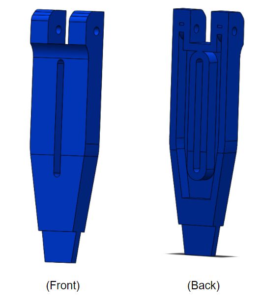
Tibia
Design Changes
- Increased size of the Femur-to-Tibia joint to prevent PLA layer splitting.
- Redesigned bottom tips to have thin rubber sheets rap around the tips for grip support while walking. In a similar way as shown in the Design Modifications Post.
Gear-to-Femurs Joints
Figure 5: Final Gear-to-Femur Design
Design Changes
- Increased Size of the joint and shape to provide exact fitment to femur end.
- Increased hole size to 3.5 mm. As recommended by the customer, we will be fitting a 3 – .5 OD bushing with ID of 2.5. We will insert a 2.5 mm screw to increase stiffness of the femur-to-gear joint while at the same time allowing the femur to go up and down.
Sensors Enclosure
Figure 6: Sensor Enclosure Design
The hardware enclosure will house: One, 3 Pin Ultra Sonic Sensor, Three, Si1145 light sensors, and 3 LEDS. The Ultra sonic and light sensors will be inserted through the top opening, and the LEDs will be inserted through the rear. The bottom hole mounts will connect to the bottom plate and the top hole mounts will connect with the top plate.
Hardware Enclosure
Figure 7: Hardware Enclosure Design
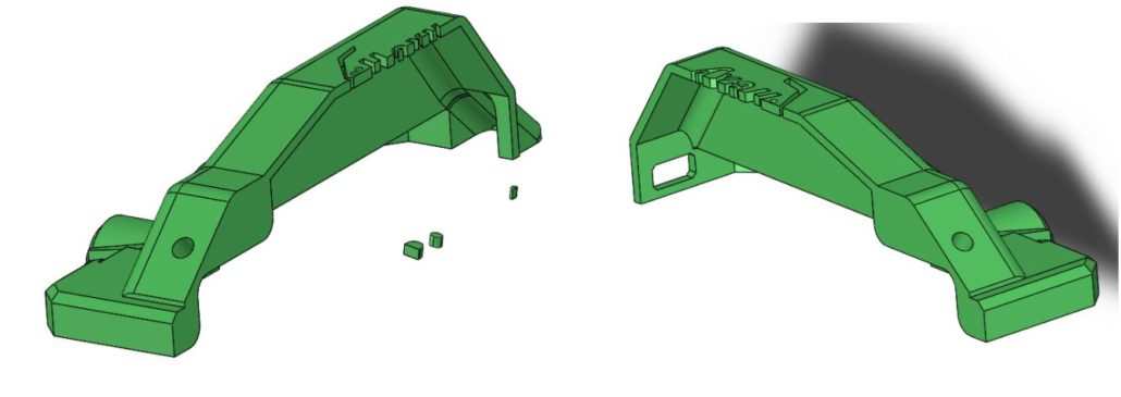
The top enclosure will give Hexy a better appearance, while at the same time concealing the hardware of our robot. The cover will have have openings for two LEDs that will act as eyes for our robot. There will be unique patterns designed in the top panel for our company logo and product name.
Figure 8: Hardware Enclosure Split in Half
Do to the size of the cover, we will be splitting it into two parts in order to not exceed the 2 hour limit on single prints.
Figure 9: Wire Tube Design
The wire tube will act as our new method to route wires from the top to the bottom plate. The opening is 15×18 mm and should be big enough to route all a=our wires to the bottom plate without interfering with our design.
Final Assembly
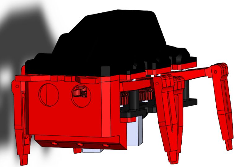
The final assembly is depicted below with the colors we plan on working with.
Figure 10: Final Assembly Front View
Figure 11: Final Assembly Rear View
Figure 12: Final Assembly Side View
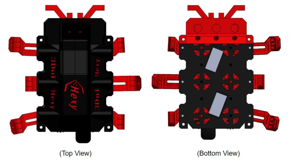
Figure 13: Final Assembly Top and Bottom View
Update 2 (April 17, 2018)
Top Plate
Figure 14: New Top Plate Design
Design Changes
- Removed gear popping mechanism from top plate. Will just add spacers to the underside of the top plate to prevent driving gears from popping.
- Added a face and holes for LEDs which will act as eyes for our spider. As requested by the customer, our Spiderbot needed to incorporate something to the top to make it stand out more and attract the eyes of the consumer.
- Center width is designed to fit the 3DoT Board which is ~ 35 mm
- Removed holes for wire routing. New hardware enclosure will include a route for wires. Also, having the wires routing through the center of the top plate would interfere with placement of hardware.
Hardware Enclosure
The hardware enclosure will conceal our hardware (as most toys typically due) and will have a design similar to that of a spider’s abdomen
New Design Assembly
Figure 16: New Design
Update 1 (April 10, 2018)
After reviewing our design with the professor and by analyzing the quality of Hexy Mk-01 we came up with the following design solutions that will solve the existing problems we have.
Chassis
Bottom Plate
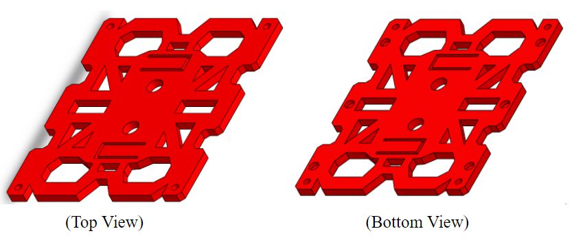
Figure 17: Bottom Plate
Design Changes:
- Removed all shaft extrusions for gears and leg guides. The reason for doing this is that these thin extrusions turned out to be very fragile when 3D printed, as explained in the assembly and fabrication blog post for 3DoT Hexy Mk-01. In multiple occasions, the manufacturing engineer (me) had to glue these thin shafts back in place. A better solution for this is to get rid of all the shafts and leave holes to insert more durable materials. Such as aluminum rods for the leg guide shafts and screws for the gear shafts.
- For the leg shaft guides, we decided to make 3.5 mm holes and insert 3 mm aluminum rods which will be cut at the desired height.
- For the gear shafts, we will leave 3.5 mm holes and do one of the following:
- Use bearings, 3 mm machine screws, and nylon locking nuts to hold gears in place.
- Use push rivets and gear inserts to hold gears in place.
- Driving gear holes will be sized to 13 mm (biggest holes shown above) in diameter for easy insert of driving gear with motor attached from the bottom plate (driving gear is 11 mm in diameter).
- Holes for leg shafts will be 3 mm in diameter (diameter of aluminum rods).
- Wires tubes designed in the top plate will be shifted to the bottom plate and will have a height of 20 mm.
- Corner holes should be 3.5 mm in diameter.
- Bottom plate thickness reduce by 2 mm to raise level of motors from ground.
- Add extruded cuts for motor boxes that are 1.5 mm deep, as shown in the bottom view above.
- Add holes for motor box mounting screws 3 mm in diameter.
Top Plate
Design Changes:
- Due to higher than expected 3D print times, we will redesign the top plate in order to have it be fabricated using a CNC machine. To do this, we will eliminate all extrusions that were present in 3DoT Hexy Mk-01. We will shift our wire tubes to the bottom plate and use a different technique to prevent the driving gear from popping off. A solution proposed by the manufacturing department is to make a three sided rectangular shaped cut out on the top plate and bend it to a degree such that the rectangle is preventing the driving gear from popping as shown below:
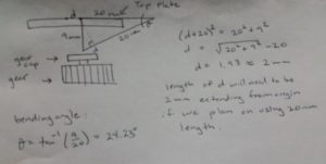 Figure 19: New Design for driving gear, gear capture
- Resized corner holes to 3.5 mm.
- Resized leg guide holes to 5 mm in diameter with 2 mm depth.
Legs
Femurs

Figure 20: Three Types of Femurs we will use
Design Changes:
- Shifted holes that connect to gear joint 2 mm inward to prevent cotter pins from braking through material.
- Rounded junction where femur-to-gear joint goes to implement new femur-to-gear joint design.
- Increased depth of extrude cut contour on the underside of femurs by 1 mm in depth.
- Increased all hole diameters to 2.5 mm.
- Increased length of tibia-to-femur joint by 2 mm.
- Rounded edges that tend to come in contact with the screws holding gears in place.
- Increased femur thickness by 2 mm to give screw holes a better placement and to reduce the probability of inserted screws ripping through material.
Tibias

Figure 21: Two types of tibia
Design Changes:
To all:
- Increased tibia thickness by 2 mm to give screw hole a better placement so that when screw is inserted it wont rib through the material.
- Got rid of narrow tips of legs and replaced them with 4.5 x 3 x 9 mm holes (length/width/depth) in order to add rubber inserts in the tips of the legs.
- Increased hole size to to 2.5 mm.
Outer Tibia:
- changed dimensions of center extruded cut to match that of the middle tibia, in order to make all legs have the same profile.
Gear-to-Femur joint
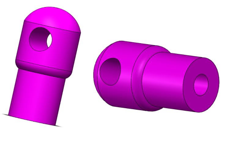
Figure 22: Gear-to-femur joints
Design Changes:
Note: This design is based of the wooden joints designed during the rapid prototype.
- New joint will be greater in diameter in the bottom (5 mm) this will provide enough space for 2 mm screw (which is the same as the diameter of the hole) to screw in without splitting open the material.
- The hole which will connect femur to joint will be 2.5 mm.
- The top is rounded to provide clearance for femurs when they are raced.
- The diameter at the bottom is smaller than that of the top due to the smaller clearance available in gears when joints rotate on gears.
Prototype – 3DoT Hexy Mk-01 (March 15, 2018)
Note: Explanations will be a derivative from the explanations given in the preliminary design document (under the mechanical drawing section). For measurements of each component that will be mentioned read the mechanical drawings document.
Chassis
The chassis of 3DoT Hexy will house: the cam system and legs, mounts for all electronic components, the lifting mechanism, and a safe passage for wires that must connect from the bottom panel to the top panel.
Bottom Plate
This design is based of Sprint 2016’s 3DoT David design. The bottom plate will house the cam system that will mimic 3DoT Davids 3:1 gear ratio design, read “ Spring 2018 3DoT Hexy: Gear Design” document. Ten shafts with 4mm diameter will be located at 21.125mm from the center axis. We will extrude cut patterns to reduce 3D print times while at the same time giving our design a unique and appealing view to distinguish it from 3DoT David. The lifting guides for the femurs will be angled. This is done in order to provide a smooth transition from ground to peak heights during the legs extension. For the holes found along the center axis: big holes will be used to run wires from top to bottom panel, and smaller holes will be used for driving motor connections. The design will have more holes upon determination of the position of the custom PCB board, battery, and 3DoT board.
Top Plate
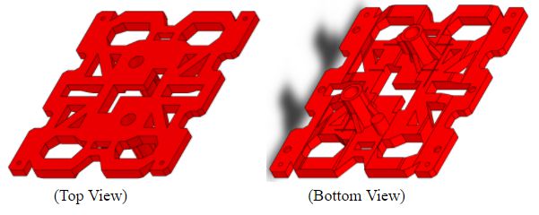
Figure 24: Top Plate
The top plate will share the same design as the bottom plate to give 3DoT Hexy a better appearance. It will be configured as a universal design, by this we mean that there will be no holes for mounting electronic components, and positioning of components can go wherever desired. Upon determination of all components being used and of their dimensions, the top plate will be reconfigured to accommodate those components in a future revision. For the most part, the top plate will be flat and showing only the extrusions. Looking at the bottom view, the small protruding shafts will be our gear captures (to keep the driving gears from popping) and the two tubes are there for wire management from top panel to bottom panel. There are holes in each corner for the screw mounts that will hold the top and bottom panel together, and there are three 1 mm deep holes on each side in which the shafts of the lifting guides will sit. We will extrude cut patterns to reduce 3D print times while at the same time giving our design a unique and appealing view to distinguish it from 3DoT David. Lastly, it may be hard to see but the thickness of the plate increases as we move closer to the center of the plate (look at mechanical sketch), this is done to provide support for the femurs when they are in there inner state of motion. If that change in thickness wasn’t there, gravity will push the femurs up making the system unbalanced when walking.
Legs
Femurs
 Figure 25: Three Types of Femurs
As explained in “Spring 2018 3DoT Hexy: Improving 3DoT David Design”, the femurs will house a groove which will provide the transition from ground level to peak height level of the legs.
Tibias
Back/Front
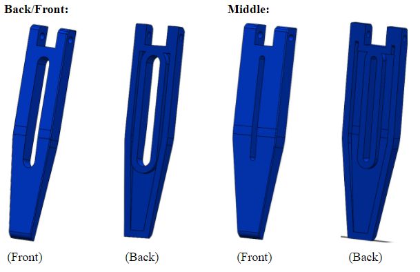 Figure 26: Two types of tibias
The legs will be wider than those of 3DoT David due to the increase width, which is needed to increase contact point of femur-to-tibia joint. The result we can expect from this is increased 3D print times due to larger surface area of tibias. To try to fix this issue we trimmed the width of the tibias by 2mm (from 6mm to 4mm) and decided to shell/hollow out the tibias and cut out excess material by making an opening right down the middle. The legs have a 2mm holes that will align with the 2mm hole of the femur. Thread will be created through this joint and a screw will be placed through femur-to-tibia joint to prevent them from moving. The design of the middle tibia is different from that of back and front tibia, the reason for this is mainly due to aesthetics. Since the middle tibia will support most of the weight, it made sense to make it look stronger than the outer tibia. For this reason, a thinner extrusion and overall wider profile was assigned to the middle tibia.
Additional Parts
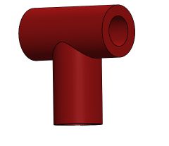
The only other component that will need to be 3D printed will be the T-joints that connect the big gears to the femurs:
Figure 27: T-joints
Dimensions for the T-joint are given in the mechanical sketch document
Cam Assembly
 Figure 28: cam assembly generated in Solidworks
Like 3DoT David’s Design, our model will follow a tripod stability model to keep the robot balanced while walking and to mimic a spider’s movement. The driving gear will be the blue D-shaped bore gears.
Completed Assembly of Hexy Mk-01
 Figure 29: Finished Assembly of 3DoT Hexy Mk-01 for prototyping
Simulation
Simulation of System Can be found by clicking the bottom link:
https://www.youtube.com/watch?v=DXkc-AGq5vk
Resources
- Spring 2018 3DoT Hexy: Mechanical Drawings
- Spring 2018 3DoT Hexy: Decision of Movement Mechanism
- Spring 2018 3DoT Hexy: Improving 3DoT David Design
- Spring 2018 3DoT Hexy: Determining Gear Design
- Spring 2018 3DoT Hexy: Preliminary Design Review

