Spring 2018: BiPed Ultrasonic Sensor Board Power Test
By: Jorge Hernandez (Electronics & Control Engineer)
Verified By: Miguel Gonzalez (Project Manager)
Approved by: Miguel Garcia (Quality Assurance)
Table of Contents
Introduction
Choosing our Ultrasonic
Power Estimates
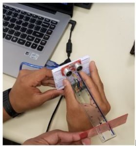
Due to the fact, the 3DoT board we are using has a 3.3V input is another huge reason we are using the SEN136B5B as it functions at 3.3V, unlike the HC-SR04. We could have used the HC-SR04 but to save space we eliminate the idea of a booster shield which will allow us to use this sensor and other 5V sensors if needed. The global current consumption was very hard to test as it only draws 15 mA according to http://wiki.seeedstudio.com/Ultra_Sonic_range_measurement_module/ which is very low and did not give me a reading when I attached it to a current sensor which would’ve given me the power estimates of this ultrasonic.
This sketch reads a PING))) ultrasonic rangefinder and returns the distance to the closest object in range. To do this, it sends a pulse to the sensor to initiate a reading, then listens for a pulse to return. The length of the returning pulse is proportional to the distance of the object from the sensor.
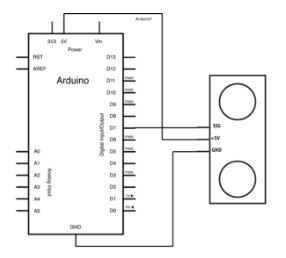
The circuit:
- +V connection of the PING))) attached to +5V
- GND connection of the PING))) attached to ground
- SIG connection of the PING))) attached to digital pin 7
Wiring & Code
*/

// this constant won't change. It's the pin number of the sensor's output:

const int pingPin = 7;

voidsetup() {

  // initialize serial communication:

  Serial.begin(9600);

}

voidloop() {

  // establish variables for duration of the ping, and the distance result

  // in inches and centimeters:

  long duration, inches, cm;

  // The PING))) is triggered by a HIGH pulse of 2 or more microseconds.

  // Give a short LOW pulse beforehand to ensure a clean HIGH pulse:

  pinMode(pingPin, OUTPUT);

  digitalWrite(pingPin, LOW);

  delayMicroseconds(2);

  digitalWrite(pingPin, HIGH);

  delayMicroseconds(5);

  digitalWrite(pingPin, LOW);

  // The same pin is used to read the signal from the PING))): a HIGH pulse

  // whose duration is the time (in microseconds) from the sending of the ping

  // to the reception of its echo off of an object.

  pinMode(pingPin, INPUT);

  duration = pulseIn(pingPin, HIGH);

  // convert the time into a distance
Power Estimates Continued
We choose to go with the Seed Ultrasonic Sensor (SEN136B5B ) as it is 3.3V compatible, the sensor was available from previous biped projects, and to meet requirements for our project which were explained above. This 3 pin ultrasonic requires power, Gnd, and a digital pin has an operating current of 15 mA and can read up to 400cm as tested.
Conclusion
We choose to go with the Seed Ultrasonic Sensor (SEN136B5B ) as it is 3.3V compatible, the sensor was available from previous biped projects, and to meet requirements for our project which were explained above. This 3 pin ultrasonic requires power, Gnd, and a digital pin has an operating current of 15 mA and can read up to 400cm as tested.


