Spring 2018: Interface and Cable Tree Blog Post
By: Jorge Hernandez (Electronics & Control Engineer)
Verified By: Miguel Gonzalez (Project Manager)
Approved by: Miguel Garcia (Quality Assurance)
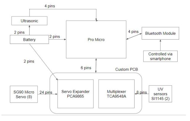
New and improved System Block Diagram for Micro Fobo which shows in a general diagram how many pins will be needed for each component and how they connect to each other. As seen we are using a total of 5 sensors, a custom PCB, Bluetooth module, external battery and of course a Pro Micro. This helps a lot for our E&C engineer when it comes to PCB designing as they need to plan accordingly.
Wiring Management
No Exposed Wires;
Wiring for sensors, Pro Micro, and PCB will not be exposed and will all be within the head of Micro Fobo.
Exposed Wires:
1/8 Inch PET Expandable Braided Sleeving with quarter inch heat shrink tubing will be used on the wires that connect the micro servos to the header
- Used to cover the wires of the SG90 micro servo
- Ensures complete coverage and protection of wires
- Clean design
The cables for the servos are routed out of the head encasement and directly to the servos through the back of Micro Fobo. Below is a photo of how clean Micro Fobo will look.


