Spring 2018 AT-ST Assembly of Custom PCB
By: Shweta Hebalkar (Electronics and Controls – Hardware)
Verified By: Intiser Kabir (Project Manager)
Approved By: Miguel Garcia (Quality Assurance)
Introduction
A custom PCB is used for less wires, clean look, and being neat as possible. This is a example of the small custom PCB made and manufactured by oshpark. This PCB has 13 surface mount components and seven through-hole parts for integration and testing of it. Customer wants us to build the PCB, implement, and integrate it into the three-dot board, which is another custom PCB (microcontroller). From that, create the design in eagle software and have him review it for approval.
Body
In this image, the surface mount is through the hole as per our requirement. For the project, we are using two UV sensors and two shaft encoders. As well as the gyroscope and the I2C expander for the UV sensor. The journey of getting it printed was rather quick because we had to pay extra for the service and shipping so we could get it on time.
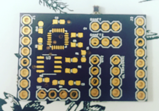
Figure 1: Blank PCB board before any short of soldering take place.
This image shows the surface mount placed on the board. It was my very first time having to surface mount components, but I got lucky and my division manager helped me. Although I could have first assembled all the parts, I was waiting for one to arrive, so I did that later on with a heat gun. I never used a heat gun before, but I looked at a few youtube videos to get a better picture. I then used a heat gun and attached my last surface mount which was the I2C expander.
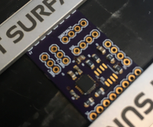
Figure 2: PCB on the pick and place machine. Having all components needed on it.
This picture shows the complete version of the board where I soldered the rest of the male headers. After that, I used a multimeter’s continuity test to see if there is a short circuit. Afterward, I mounted this on the new version of the three dot board.
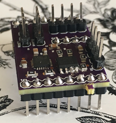
Figure 3: PCB with all components on.
Conclusion
Overall I learned a lot in this class, like time management, keep working till you get the answer, and communicate with others. The PCB works fine and all that is left is to integrate it to the AT-ST robot!