Spring 2018 AT-ST Cable Tree
By: Samuel Yoo (Electronics and Controls Software Engineer)
Danny Pham (Manufacturing and Design Engineer)
Verified By: Intiser Kabir (Project Manager)
Approved By: Miguel Garcia (Quality Assurance)
Table of Contents
Introduction
This blog post shows the wiring design for the AT-ST robot. It will show how the wires connect from the board inside the box to the servo, ultrasonic sensor, and the motors outside of the box on the final model images.
The wiring for the AT-ST robot contains only ribbon wires. There were two different types of cables, one with the female-to-female connector and the female to male connectors. The female to male connectors were store bought and used for the ultrasonic sensor and the servo. The female-to-female connectors were made from components and used for the dc motor only. There are two methods of making these type of wires; the first one is soldering a wire with a male connector and a female connector with male pins. After soldering the part together place, shrink wire on the connections and heat up the wire to get a good conductivity. The other method is getting a ribbon cable, housing, and female pins. With the listed components, first, remove some of the plastic off the wire to get the metal. Then taking the female pins, crimp them on the ribbon cable. After that step is done for each wire piece, insert them into the housing.
Wiring
- Wires – Red
- Board – Black box Green outline
- Connectors – Black box
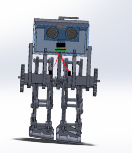
Description: Front image of the wiring design. It shows wires connecting from the motors through the hole in the box to the board. The wires connect from the ultrasonic sensor inside the box directly to the board.
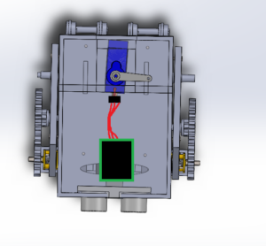
Description: Top image of the wiring. The wires connect directly from the servo to the board.
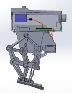
Description: Side view of the wiring design. It shows the wires connecting to the board from the servo and the motors.
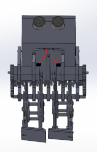
Description: Front angled image of the board. It shows a better view of the hole on the bottom side of the box and the wires connecting from the motors into the box.
Conclusion
The connectors for the wiring made it much easier to connect and disconnect the electronic parts. Some other issues with this design are that since the final model is not closed, there are a lot of gaps that wires come through that aren’t hidden. A simple solution to hide the wires is to design new panels that would go on the front that will hide the motor wires.
References
- Final 3D Model Blog post: Linked when Published
- Interface matrix: https://www.arxterra.com/at-st_interface_matrix/


