Tutorial on Fast Pulse Width Modulation
Many of the labs in this document employ fast pulse width modulation (PWM) as implemented by one or more of the Atmega32U4’s four (4) timer peripheral subsystems. This chapter is included for those developers who are not familiar with fast pulse width modulation and/or the timer peripheral subsystems of the Atmega32U4.
Modes of PWM
Pulse Width Modulation (PWM) is a technique for outputting analog voltage levels using digital means. What this means is that these pins output a square wave signal that oscillates between on and off. This oscillation essentially produces voltage levels between 0 and 5 volts depending on the duty cycle of the signal and is controlled using the “analogWrite(pin, value)” function where ‘pin’ is the pin that you are writing to and ‘value’ is a value between 0 and 255. Inputting the value 0 will result in a square wave with a 0% duty cycle and produce 0V (always off), inputting the value 127 will result in a square wave with a 50% duty cycle and produce 2.5V, while inputting the value 255 will result in square wave with a 100% duty cycle and produce 5V (always on). Any value in between 0 and 255 will result in a duty cycle between 0% and 100% correspondingly. Sample PWM signals produced with varied values can be seen below in Figure 16.1.
Figure 16.1: Values varied for the “analogWrite()” function and their resulting PWM signal.
PWM has several applications. A few are:
- Dimming an LED
- Providing an analog output; if the digital output is filtered,
it will provide an analog voltage between 0% and 100%. - Generating audio signals.
- Providing variable speed control for motors.
- Generating a modulated signal, for example, to drive an infrared LED for a remote control.
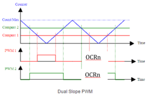
Now, there are two main operating modes of PWM: phase-correct PWM and fast PWM. To briefly explain the difference between the two, in phase-correct PWM mode the timer counter counts up and down (generating a triangle wave). When the counter reaches the compare bit, the PWM signal will be high, and when the counter counts back down below the compare bit the PWM signal will be low. Characteristics of phase-correct PWM are that the pulses are wider and that the middle of OCRnA and OCRnB are in alignment (where OCRnA and OCRnB are two separate PWM pins connected to the same timer counter) as shown in Figure 16.2.
Figure 16.2: Phase-correct PWM.
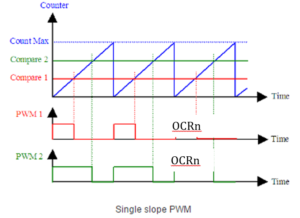
In fast PWM mode, the timer counter counts up and then drastically drops down to zero again (generating a sawtooth wave). When the counter reaches the compare bit, the PWM signal will be high, and when the counter drops back down, the PWM signal will be low. Characteristics of fast PWM are that it is twice as fast, the pulses are narrower, and that the rising edges of OCRnA and OCRnB are in alignment as shown in Figure 16.3.
Figure 16.3: Fast PWM.
Phase-correct PWM is the type that most of the PWM pins on the Arduino operate at, while the only pins that operate using fast PWM are the pin(s) that utilize Timer Counter 0. It is not a good idea to mess with Timer Counter 0, because this is the timer that Arduino uses to create the delay() function. However, this lab will show how to convert all PWM pins in phase-correct mode to fast mode.
Fast PWM with the Leonardo
|
Note: This Tutorial is focused on Leonardo, needs to be refocused for 3Dot |
For learning PWM modes for the 3DoT, begin with using the Arduino Leonardo since it uses the same microcontroller, the Atmega32u4. The reason this lesson will be taught on the Leonardo rather than the 3DoT is that the Leonardo has header pins which we can easily access each digital output.
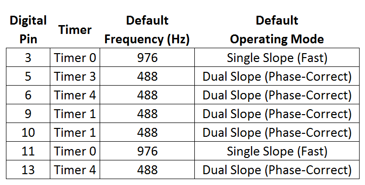
There are seven PWM pins on the Leonardo. These are pins 3, 5, 6, 9, 10, 11, and 13. These pins are easily identifiable as digital pins capable of PWM by the tilde symbol (~) right next to each of these numbers. These pins belong to the following timer counters, and are pre-programmed to operate in the following PWM modes seen in Table 02 below. The digital pins that use Timer 0 and are in fast PWM mode have a frequency that is twice as fast as the frequency of the pins that are in phase-correct mode, which is consistent with what has previously been explained.
Table 16.1: PWM modes for each digital pin on the Arduino Leonardo.
First, set up a test code to verify that each pin on your Arduino Leonardo really produces the frequencies specified above. Download the following code.
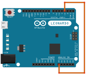
In this test code all the PWM pins on the Leonardo are set to output a PWM signal. Furthermore, Analog Pin 0 (though any I/O pin could be used) is set as an input to read the frequency of generated PWM pins. To test the frequency of each pin, simply start with connecting pin 3 to A0 as shown below in Figure 16.4.
Figure 16.4: Connect pin 3 to A0.
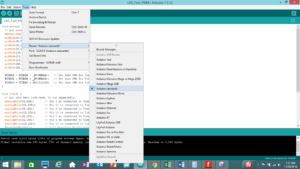
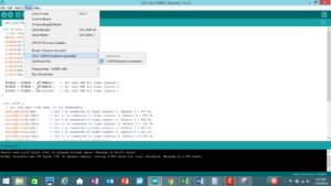
Make sure the board is plugged in and the proper board and COM port are chosen in Arduino IDE as shown in Figure 16.5:
Figure 16.5: Choosing the correct board and COM port.
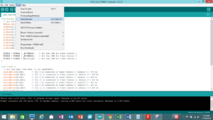
Upload the code to the board and open the “Serial Monitor” window as shown below in Figure 16.6:
Figure 16.6: Opening the “Serial Monitor” window
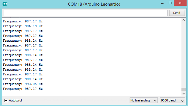
Now, if pin 3 was started with, the frequency displayed in the Serial Monitor should be around 976 Hz, which is consistent with Table 02. Next, move on down the list of the PWM pins (5, 6, 9, 10, 11, and 13) and continue to measure the frequency of each pin. Verify that the recorded data matches up with Table 02. Please note that this Arduino frequency reader is not 100% accurate so the experimental values will be slightly off.
Next, begin converting each pin that is operating in phase-correct PWM mode to fast PWM mode. First, start with Timer 1, which generates PWM signals for pins 9 and 10. In Timer Counter 1, the PWM operating mode is controlled in the TCCR1A and TCCR1B registers as shown in Figure 16.7.
Figure 16.7: Timer counter 1 PWM operating modes controlled by registers “TCCR1A” and “TCCR1B”.
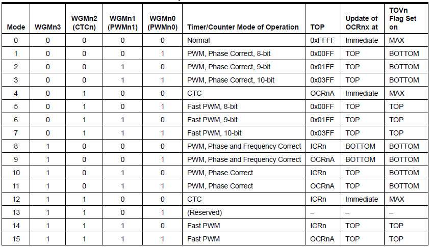
Each pin is important and has a specific purpose but only focus on the ones with PWM operating modes which is controlled by the “WGM12”, “WGM11”, and “WGM10” bits. Table 16.2 below shows what each bit should be set to in order to achieve various PWM operating modes.
Table 16.1: Pin values and corresponding PWM operating modes.
To achieve fast PWM, “WGM12” should be set high to ‘1’. The easiest way to do this is to use the “inbuild _BV()” function in Arduino IDE. Copy and paste the following code at the end of “setup()”. Through using the OR command, set the “WGM12” bit in the TCRR1B register high without altering any of the other bits.
TCCR1B = TCCR1B | _BV(WGM12); // Set fast PWM for Timer Counter 1
Next, convert Timer 3, which controls pin 5, to fast PWM mode. This is very easy and similar to Timer 1. Copy and paste the following code below the line at the end of “setup()”.
TCCR3B = TCCR3B | _BV(WGM32); // Set fast PWM for Timer Counter 3
Last, converting Timer 4, which controls pins 6 and 13, is a bit different. Its PWM functionality is controlled through the TCCR4D register as follows in Table 16.3:
Table 16.3: Values to convert Timer 4 using the “TCCR4D” register.
So to make Timer 4 operate in fast PWM mode, clear the WGM41 and WGM40 bits in the TCCR4D register shown in Figure 16.8:
Figure 16.8: Bits of “TCCR4D” register.
This is easily achieved through using the AND command with zeros in the place of bits ‘0’ and ‘1’ and ones for bits 7:2 in order to not manipulate any of the other bits. Copy and paste the following code at the end of “setup()”.
TCCR4D = TCCR4D & 0b11111100; // Set fast PWM for Timer Counter 4
Run the code, open the “Serial Monitor”, and measure the frequency of each pin. You should find that the frequency of pins 5, 6, 9, 10, and 13 have doubled. Again, this is from converting each pin from operating in phase-correct mode to fast mode, which operates at twice the speed. Verify that these pins now generate PWM signals with a frequency of 976 Hz.


