EagleCAD Schematic Capture
Table of Contents
Introduction
Cadsoft EagleCad is ubiquitous within the Arduino Open Source community. For this reason when a CAD file is made freely available to the open source community it will most likely be as an EagleCAD file type. For example, all modules sold by Sparkfun are open-source and made available as EagleCAD files. The downside of EagleCAD is its archaic and illogical user interface and the very high cost of moving from the FREE version, which supports only 2 layers to the professional version, which supports up to 15 layers are a cost of $1,700. On the other hand you could download DesignSpark (2010) PCB, KiCad EDA Software Suite (2007), gEDA GPL’d suite and toolkit of EDA tools and have up to 14 layers for FREE, or PCB Creator by Bay Area Circuits. The downside is you will need to make your schematics and PCB layouts from scratch or attempt to import an Eagle file. This document covers DesignSpark (2010), with its very intuitive graphical user interface and Eagle import tool.
Remember no matter which CAD tool you use,
![]() Save Often
Save Often
Tutorials
Arduino example project by Sparkfun
Schematic: https://learn.sparkfun.com/tutorials/using-eagle-schematic
The previous tutorial is an earlier or later version of the following tutorial series, which are all in the above version (1 page versus 3).
https://learn.sparkfun.com/tutorials/using-eagle-schematic/adding-parts-to-a-schematic
The SparkFun Eagle Library: https://github.com/sparkfun/SparkFun-Eagle-Libraries
The readme file includes useful information and learning links
Part Design
Designing PCBs: SMD Footprints https://learn.sparkfun.com/tutorials/designing-pcbs-smd-footprints
This is another footprint-making tutorial. This one details a unique process using digital imagery to create the part.
Making Custom Footprints https://learn.sparkfun.com/tutorials/making-custom-footprints-in-eagle
In addition to the Arduino Sample Project, Sparkfun has a Beginning Embedded Electronics series.
Lecture 1 – Background and Power Supply
Lecture 2 – How to Get Code onto a Microcontroller
Lecture 3 – What is an oscillator?
Lecture 4 – UART and Serial Communication
Lecture 5 – AVR GCC Compiling
Lecture 6 – Soldering Basics
Lecture 7 – SMD Soldering
Lecture 8 – Eagle: Schematics
Lecture 9 – Eagle: PCB Layout
Lecture 10 – Eagle: Creating a new part
Common Mistakes, Tips and Tricks
Sparkfun Video – Tips and Tricks
https://learn.sparkfun.com/tutorials/using-eagle-board-layout
- Free mug – feedback@sparkfun.com, subject line According to Pete
- Nice beginner tips that all students should know!
- Does not recommend Vcc pour on top layer
- Label your pins
- Testing – Limit power supply to like 100mA. This could have saved us a board. Also recommends measuring resistance.
Working from an Existing Design
How to merge board/schematic pairs using the PASTE function with full consistency can be found here.
The Schematic
The Basics
Finding Parts in Eagle
(1) Find Breakout Board in Sparkfun (2) Download Eagle Schematic (3) Copy – Paste part to your schematic.
- Here’s the step-by-step (source: Copying from one design to another in EAGLE).
- Open your schematic (doesn’t work on board layouts).
- Group the objects you want to copy
- Click “cut”. Right click on the group you just created (or just click “go”).
- Open the schematic you want to paste to BY CLICKING THE “OPEN” BUTTON ON THE
- TOOLBAR OF THE SCHEMATIC EDITOR.
- Click “paste”.
Neither of the following works. The paste buffer is specific to the instance of the schematic editor you have open, so if you close it, you lose it.
- Opening two schematics in two separate instances of the Schematic editor
- Opening the “from” schematic, copying, closing the schematic editor, then opening the “to” schematic, and trying to paste.
Sparkfun Library
First download the Sparkfun Library found here. Review this tutorial. Eagle does not use any of the libraries by default (dumb!).
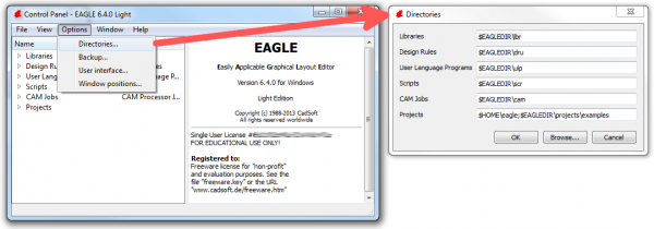
Back to the EAGLE Control Panel window now. Go to the “Options” menu and then select “Directories”. This is a list of computer directories where EAGLE looks when it populates all six objects in the tree view…including libraries.
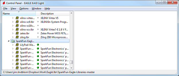
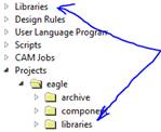
Right-click on the “SparkFun-Eagle-Libraries-master” folder, and select “Use all”. Then check the libraries in each of the two folders. Next to them should be either a grey or green dot. A green dot next to a library means it’s in use, a grey dot means it’s not. Your libraries tree should look a little something like this:
To find a part select add part icon in schematic window and use find.
Bluetooth HC-05/HC-6 Module
Hochschule Luzern has been nice enough to share his Eagle HC-05 Part on GitHub along with a sample project. He designed this material for his students of the INTRO (Infotronic) course at the Lucerne University of Applied Sciences and Arts to have some fun with building and programming Mini-Sumo Robots
Schematic Frame
How to Find/Add a frame
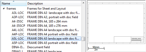
In schematic view, click the add part ![]() icon, then search, then enter “frame”.
icon, then search, then enter “frame”.
https://learn.sparkfun.com/tutorials/using-eagle-schematic/adding-parts-to-a-schematic
Align frame to bottom left edge. 
Frame will say not saved. It is supposed to show the last date saved when you save the file. It would not do this for me unless schematic window was closed and then reopened.
How to Add/Move/Delete frame component (actually any component part)
Must select origin (lower-left for frame, but not title box) To move both, select as group, right-click origin (lower-left), select move as group, move to origin. Example provided in this video.
Video Tutorial
- How to Create a Project
- Stop Copying the Part by Clicking move tool icon

- Move a Part with individual Components
- Click group icon, select components, right-click, select move
- You can only delete
 one component at a time (even if you group them)
 - Now copy tool
 copies all the individual components of the part
So you are saying that all the basic tools behave differently!
- Tutorial 2 ends with name and value icons. You can also access these properties by right clicking the part and selecting properties.

Wiring up the Schematic
Sparkfun
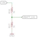
Do not use the WIRE tool ![]() to connect parts together. Instead, use the NET tool
to connect parts together. Instead, use the NET tool ![]() (left toolbar, or under the Draw menu). The WIRE tool would be better-named as a line-drawing tool; NET does a better job of connecting components.
(left toolbar, or under the Draw menu). The WIRE tool would be better-named as a line-drawing tool; NET does a better job of connecting components.
![]()
Stack Exchange
In Eagle, right click on the label (or add one to the net first), choose properties and check the Xref box and click OK. I think the accurate name for these is Cross-References. Source: stackexchange
Video Tutorial
- Discovered by accident if you select move and then double click a part which touches a wire it will connect You could also use the connect tool

- Zoom to Fit is a nice tool

- Tutorial Lesson 5 show how you can right click to rotate part before you drop it, you can also click on a mirror icon while you have it to mirror the part.
- Click on this icon on the top menu bar
 to switch between the schematic and the board.
 - Use the grid tool to set and display the grid size.
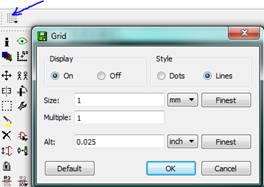
- The FIRST TIME YOU MOVE A PART you must CTRL click to snap to grid.
- Lesson 6 shows how to set board dimensions. Pretty simple, select move tool click on an edge (not origin) and viewing grid location (upper left hand corner of display) set the edge down where you want it.
- The show tool
 mentioned in lesson 7 does not work (blinks out) if you click on the switch views using the switch
  icon. Instead open both windows and click between them.
 - Lesson 8 shows how once you got things lined up (changed grid to 0.2) you use the rat nest cleanup tool
 to clean everything up.
How to Restore a Library
Actually, I ran into this problem at the start of the tutorial when I first clicked the add part button and a window opened without any parts in it. I found the solution here. In the Eagle Control Panel right click on the library folder(s), all you can find, and choose “select all.”
The author presents a similar solution starting about 9 minutes into video.
Creating a Custom Library Part
How to Export the Parts Libraries from a Schematic file (.sch)
Where do I find SmartPrj CAD Library
By using Eagle 6 built in exp-librs.uld (tutorial provides an earlier version) I was able to export two libraries from Arduino Leonardo SmartPrj.lbr and MyPOW.lbr (my power). I then placed these two libraries in the Eagle Library folder. Received a lot of error messages, but it seems to have worked. As a test I was able to a second ATmega32U4 part.
CadSoft EagleCAD Tutorial
Creating a Part Library – Lesson 1 in a New CadSoft video series. Everything in Eagle is on a 0.1 inch grid. From the control panel select File New Library. Talks about part naming convention which is nice.
I accidently found his custom library folder hiding here rpc-electronics.com/eagle/
Each part needs a symbol, package, device definition ![]() (shown in reverse order). Lesson 2 talks about how to define the Symbol
(shown in reverse order). Lesson 2 talks about how to define the Symbol ![]() . Start from the data sheet. Lesson 3 talks about how to define the Package
. Start from the data sheet. Lesson 3 talks about how to define the Package ![]() for a through hole part. Lesson 4 talks about how to define the Device
for a through hole part. Lesson 4 talks about how to define the Device ![]() Lesson 5 shows how to define a surface mount part. Unfortunately, cannot find Lesson 5.
Lesson 5 shows how to define a surface mount part. Unfortunately, cannot find Lesson 5.