Lab 3B: Pseudo-instruction HitWall, LeftPaw, and RightPaw
This lab sequence (3a and 3b) is all about subroutines. In part one (Lab 3a) you were given two new subroutines named DrawRoom and DrawDirection, which implemented your code from Labs 1 and 2. In part A of this lab, you wrote your first three pseudo-instructions (implemented as subroutines) named TurnLeft, TurnRight and TurnAround. In addition to these three new pseudo-instructions you wrote a subroutine named WhichWay to test them. Hopefully by now you realize that subroutines can clean up your code and make it more readable. In part one (lab 3A) you also learned a few rules about how to make a nice general purpose subroutine.
In this second part of the lab you will now discover that subroutines can act as building blocks in the construction of more complex programs. Specifically, you will now use subroutines DrawRoom, DrawDirection, TurnLeft,and TurnRight in more than one place to solve what initially may appear as an unrelated problems.
First, you will use the two subroutines I provided to you (DrawRoom and DrawDrection) to write a new general purpose subroutine named HitWall. You will then write two new subroutines named LeftPaw and RightPaw using subroutines TurnRight, and TurnLeft from lab 3A and your new HitWall. One unexpected benefit you will discover, is that you can write all these new subroutines (HitWall, LeftPaw,and RightPaw) while only needing to learn a few new assembly instructions (and, tst).
Table of Contents
What is New?
Here are some of the new concepts you will be exploring in this lab.
- Application of a general purpose subroutine
Here are some of the new instructions you will be learning in this lab.
AVR Assembly Instructions
Arithmetic and Logic
tst r24 // r24 = r24 & r24
and r24, r16
Pseudo-instruction HitWall
In this part of the lab you are going to start helping the bear to explore a room by answering the question “Did you hit a wall?” Within your assembly program you will ask the question by calling a new subroutine named HitWall. To answer the question, your new subroutine will need to know the room the bear is currently in and the direction the bear is facing. This information is saved in variables room and dir respectively.
While the subroutine could directly load variables room and dir, we will continue to follow our programming practice of sending arguments as required by the gcc C++ compiler for mixed C++/Assembly programming.
Sending Arguments as Required for Mixed C++/Assembly Programming
In a mixed C++/Assembly application program, the first argument is sent in the r25:r24 register pair, the second in r23:r22, the third in r21:r20, etcetera. In the past, now, and in the future we will assume the most significant register of the pairs (r25, r23, r21,…) are zero. For our HitWall subroutine we will somewhat arbitrarily send the direction dir variable in r24 and the room in r22. So how do these variables get in the registers? The answer to this question leads to the basic structure of all our subroutine calls.
lds r24, dir // first argument
lds r22, room // second argument
call HitWall
In a similar fashion to the calling arguments being sent in these register pairs, function return values are returned in the same registers in the same sequence – r25:r24 register pair, the second in r23:r22, the third in r21:r20, etcetera.
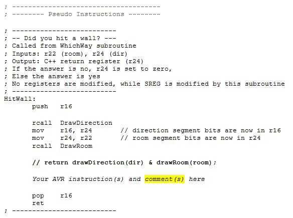
Write a new subroutine named HitWall using register r22 (room) and register r24 (dir) as arguments and using byte-wide logical operators (com, and, or) such that if the answer to the question is no (the bear did not hit a wall) the r24 register is set to zero.
Conceptually, we want to first, using our new subroutines DrawDirection, and DrawRoom, convert SRAM variables dir (now in register r24) and room (now in r22) into their respective 7-segment images. Now that the bits have been aligned to a segment we want to test if the bit set to 1 in r24 (a wall in the room) corresponds to a bit set to 1 in r16 (the direction the bear is facing). If it is, we want to set the register r24 to a non-zero value. I have provided the C++ equivalent statement as a comment to help you get started.

Write a Subroutine to Test HitWall
To find out if your new HitWall pseudo-instruction works, add the following call to TestHitWall in your main loop after the bear’s direction has been updated from WhichWay. The TestHitWall as the name implies a temporary subroutine we are adding simply to verify the operation of the HitWall subroutine. As such it has no calling arguments and will itself load up the arguments for our HitWall subroutine.
In the following test code, I send the answer to the question to two of the discrete LEDs on the Arduino Proto-Shield. This is a great way to track your programs as they become more complex.
This is a temporary subroutine only intended to test if the HitWall subroutine works. For this reason the subroutine does not have to be callable from C++ and therefore does not follow our rules for passing arguments in registers (e.g. r24, r22).
Place your TestHitWall in the test subroutine area of your code.
Update Code

The above subroutine introduces the “Test for Zero or Minus,” mnemonic tst instruction. The tst instruction, like the compare instruction, is used to modify SREG flag bits, without modifying any operands. For our test, we are interested in the zero flag, which will be set if r24 = 0, and 1 otherwise. We then test the Z flag bit using the branch if equal (breq) instruction in order to take the correct action (turning on and off two test LEDs).
Test the HitWall Subroutine using the Proto-shield
As you have hopefully learned, it is always a good idea to test your code as often as possible. Using the TestHitWall subroutine test your HitWall subroutine on the protoshield. If it does not work simulate the program and locate the bug. The next two subroutines you will write call HitWall, so if it does not work, neither will they.
Pseudo-instructions RightPaw and LeftPaw
Our programming goal in this part of the lab is to continue to help the bear explore a room. Specifically, we now want to teach the bear to answer the questions “Can your right paw touch a wall?” and Can your left paw touch a wall?”
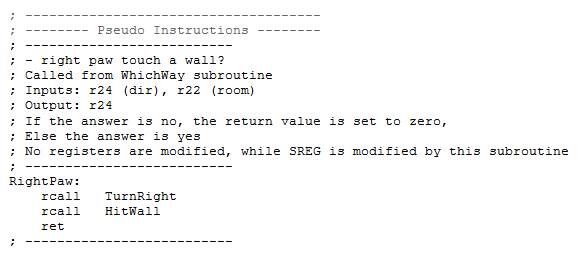
Here is my RightPaw subroutine using subroutines TurnRight and HitWall as building blocks . If the answer to the question is yes (the paw touches a wall) then I return a value not equal to zero.

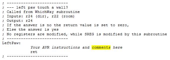
By using RightPaw as a guide, write LeftPaw.

Test RightPaw and LeftPaw using the AVRStudio Simulator
Verify the basic operation of your RightPaw and LeftPaw subroutines using the AVR Studio Debugger. Remember, before you debug/run any program you should know what values will be contained in the effected variables (RAM) and registers. In this case you want to
- Run to ReadSwitches
- Set the maze and direction switches (your choice)
- Set a breakpoint at the entry to both RightPaw and LeftPaw.
- Watch r22 and r24
- Step over each subroutine and see if register r24 is being correctly set to TRUE or FALSE based on the switch positions you set.
- If you are not getting the answer you are expecting, reset the simulator, repeat steps 1 to 5, and this time step into the subroutine to be debugged. If everything looks good, repeat steps 1 to 5 until you are happy that your subroutines are working.
Test RightPaw and LeftPaw using the Proto-shield
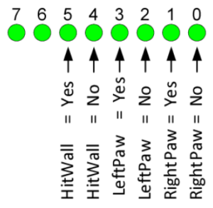
Using my TestWall code from the previous lab as an example, write two new test subroutines named TestRightPaw and TestLeftPaw, to find out if your two new pseudo-instructions RightPaw and LeftPaw really work. Send the answers to the questions to four new discrete LEDs on the Arduino Proto-Shield board as defined below. Notice that an LED will light if the answer is yes or no. This allows positive feedback whether or not your subroutine is even being called. For example, if you only had an LED light up if the answer was yes, how would you know the difference between a subroutine that was never called and a subroutine that was called but always returned no?
Call TestRightPaw and TestLeftPaw from your main loop as shown below.
loop:
     /* start of the loop (readswitches, update variables) */
     sts turn, r17
     lds r24, dir
     lds r22, turn
     rcall WhichWay
     sts dir, r24
     rcall TestHitWall
     rcall TestRightPaw
     rcall TestLeftPaw

     /* Draw Direction */
     lds r24, dir
     rcall DrawDirection
     ....
     /* other code */

     ....
     call WriteDisplay
     rjmp loop
Using AVR Studio, simulate your new Test programs and then download and test your completed program. Like you, I always just download and then test. I mean who wants to wait! And like you the first time I tested my new subroutines they did not work. In AVR Studio I first set and ran to a break point at rcall DrawRoom. I did this to make sure my I/O ports had been configured. I then set my pin values on Ports D and C to match my switch settings and ran to a break point at the end of my program rjmp loop. I then looked at register r9 (spiLEDS) to confirm that what I saw on the board was what I saw in the simulator. That is a good thing; because, it means that I can find the bug using the simulator. I then set a break point at the beginning of TestRightPaw so I could single step and watch my test bench and new subroutines in action.
Debug Tips
Run a simulation on the main loop – enter a value and see if the output matches the simulation. If yes you can isolate quickly to the problem. If not you are missing something. Verify r8 and r9’s value every time WriteDisplay is called.
Common mistakes… Subroutines must input and output r22 and r24 only!!!! They must not modify any other registers like spi7SEG, spiLED, r8, or r9. They must not call WriteDisplay. The registers must be updated after the calls along with you call to WriteDisplay. Do not clear any registers like r8 or r9 within the main loop or in the subroutines. Verify that the stack does not change within the main loop. Again try and find out how or if the simulation output is different from what you are seeing on the upload version.
Design Challenge and Creative Corner
If you have not completed the Lab 3 Design Challenge or the Creative Corner; defined at the end of Lab3a you may do so at this time.
Lab 3 Deliverable(s)
STOP Read the Lab READ ME document contained in the Labs Folder. Be absolutely sure you have followed all instruction in the “Lab Formatting” section of this document. Points will be deducted if you do not follow these instructions. You have been warned.
Make sure your lab notebook is up to date. Follow the guidelines provided in the “Lab Notebook” section of the Lab READ ME document.
Make sure you have read and understand the “Plagiarism” section of the Lab READ ME document, especially if you are repeating the class.
All labs should represent your own work – DO NOT COPY.
Table of Contents
- Basic Lab
a. Main Program (Title Block, Initialization, Main Loop)
b. Subroutines (WhichWay, LeftPaw, HitWall, TurnRight, TurnAround, TestHitWall, TestRightPaw, and TestLeftPaw) - Design Challenge – Turn using Indirect Addressing Mode or Display

