Lab 4A: Timers — Polling
Steps to Program a Simple Delay (Normal Mode)
With the introduction of subroutines, things are now more organized; however, it is still difficult to distinguish between a room segment and a direction segment. In this lab, you will solve this problem by writing a software polling routine using Timer 1 to toggle the direction LED on and off with a period long enough for you to see it blink (2 Hz).
Table of Contents
What is New?
Here are some of the new concepts you will be exploring in this lab.
- Implementing a Finite State Machine (FSM) in software.
- Working with Timers and Counters
No new assembly directives or instructions are introduced in this lab.
Create the Lab 4A Project
If you are using a lab computer I would recommend erasing everything in Drive D and using this area for our project. Do not forget to save often. At the end of the lab do not forget to save to your Flash drive.
- Open AVR Studio and create a new Project named Lab04 (see Lab 1 for detailed instructions)
- Copy over spi_shield.inc, testbench.inc, and upload.bat from Lab03.
- Open the upload.bat file in notepad (right-click edit) and change the file name from Lab03.hex to Lab04A.hex
- Copy the text in Lab03.asm into Lab04A.asm
- Update the information in the title block.
- Build your project and verify you are starting with zero errors and zero warnings.
Build pseudo_instr Include File
At this point your program has become fairly large and hard to manage. To simplify things a little you are going to make a new include file to hold the pseudo instructions that you completed in the last lab.
- In AVR Studio open a new file (File – New File)
- Cut and Paste the following material from your Lab03B.asm file over to this new file.
a. Subroutines TurnLeft, TurnRight, TurnAround, RightPaw, Leftpaw, and Hitwall
b. If you like you can also move or simply delete the test routines for these subroutines (TestHitWall, TestRightPaw,and TestLeftPaw)
c. Move and/or delete any assembly directives (.EQU, .DEF) associated with these subroutines. If you have done the basic lab sequence, you probably did not write any new assembly directives. - Save the file with the name pseudo_instr.inc
- Assemble and upload to your board. Verify that your program is still working.
- Make a backup copy of your project folder so you can return to a working program if needed.
Lab Reset
Now that you know that your pseudo instructions work you no longer need the test bench code created in Lab 3 (A and B).
- Download and unzip my Lab03.zip
- Open the Lab03.asm file (File – Open) in AVR Studio.
- Select All the text in Lab03.asm (CTRL-A, CTRL-C) and copy over your to your Lab04A.asm file (CTRL-A, CTRL-V).
- Close the Lab03.asm file (you no longer need it).
- In your main program (Lab04A.asm) add the INCLUDE assembly directive to include your new pseudo_instr.inc file.
.INCLUDE “spi_shield.inc”
.INCLUDE “testbench.inc” // DrawDirection and DrawRoom
.INCLUDE “pseudo_instr.inc” // Pseudo Instructions - Assemble and upload to your board. Verify that your basic program is still working. Specifically, you can draw a room and direction.
Delay
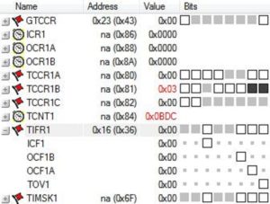
In the initialization (reset) section of your code set the Timer 1 prescale value and start Timer 1. You may also want to initialize the TCNT1H:TCNT1L register pair.
call InitShield
; Set prescale and start Timer/Counter1
; Add your code to initialize Timer Counter 1 (TCNT1) from the pre-lab
; and add comments explaining the code.
ldi r16,(1<
sts TCCR1B,r16 // Clock Select Bit Description
The C++ bit-wise left shift operator
The C++ bit-wise left shift operator << is used to move a one (1) into a specified bit location within a byte. In the first half of the expression an 8-bit value is built with the CS1 bit 1 set to 1 ( 0b00000010).In the second half of the expression an 8-bit value is built with the CS1 bit 0 set to 1 ( 0b00000001). The C++ bit-wise or operator | is used to combine these two bytes to form the byte to be stored in register r16 (0b00000011).
Add the Delay subroutine from your answer to Question 3 in your pre-lab.
; ————————————-
; ——- Support Subroutines ———
; ————————–
; —— Delay 250ms ——
; Called from main program
; Input: none Output: none
; no registers are modified by this subroutine
Delay:
push r16
wait:
Place your commented polling routine from pre-lab question 3 here
pop r16
ret
Testing Delay using the Proto-shield
You have now added a subroutine to generate a delay of 250 ms, but how will you know it really works? In this section we will add the toggle code you wrote in the prelab.
Define a new byte variable named next_state. Later in the lab you will be generating a 2-state Finite State Machine (FSM), at which time this name will hopefully make sense.
.DSEG
room: .BYTE 1
dir: .BYTE 1
next_state: .BYTE 1
.CSEG
This is the third variable we have saved in SRAM, so let’s review what is happening. The .DSEG assembly directive tells the AVRStudio assembler that we are going to be talking about the Data Segment (DSEG). The .BYTE assembly directive tells the AVRStudio assembler that we want to reserve N bytes of RAM whose starting address should be associated with the specified name. In this example the variable name is next_state and the number of bytes to be associated with this name is 1.
We will be using variable next_state to tell us if the direction bit is currently ON or OFF. A good programming practice is to initialize all variables on reset. Within the reset section of your program clear variable next_state.
clr r16 // your comment here
sts next_state, r16
Call Delay
Place your code to toggle next_state from the prelab (Question 4) at the beginning of the loop section of your program as shown here.
loop:
call ReadSwitches // read switches into r7
/* Read Switches and update room, direction, and turn */
Block of code to update variables room and dir based on switch values.
// state = next_state;
lds r20, next_state // toggle next_state (prelab question 4)
___ ___, ____
___ r20, ____
sts next_state, r20
Include your code to blink the discrete LEDs and your call to the Delay routine at the end of the loop section after drawing the room.
/* Room Builder */
lds r24, room // calling argument room is placed in r24.
rcall DrawRoom // translate room to 7-seg bits
mov spi7SEG, r24 // return value is saved to 7 segment display register
call WriteDisplay // display the room
/* update discrete red LEDs */
Insert your solution to prelab question 5 here
call WriteDisplay
rcall delay // insert a delay of 250 ms
rjmp loop
Verify that your new code is working before proceeding to the next section. You may need to simulate, in which case be sure and follow the debug tip here and keep the TIMER_COUNTER_1 window open.
You may notice that the LEDs do not change as quickly as before. This is a by-product of polling which blocks all other instructions from being executed until the 250 ms delay times-out. You will have a chance to correct this problem by accepting the design challenge.
Debug Tip 1
Waiting for a 16-bit Timer/Counter to time-out in a simulator even when you are simply running the simulation ![]() (not single stepping
(not single stepping ![]() the program) can take a long time.
the program) can take a long time.
You have two ways you can set the overflow flag. The simplest is to set a breakpoint anywhere in your loop and once the program is stopped manually set the overflow flag bit.
You can also speed things along during testing by short-counting the first time-out and resetting the count in the Delay subroutine, by initializing the timer/counter to a relatively high value as shown here.
ldi r16,0xFF // Short-count (originally 0x0B)
sts TCNT1H,r16
ldi r16,0xDC // load value low byte
sts TCNT1L,r16
DO NOT FORGET TO PUT THE ORIGINAL TIMER VALUE BACK ONCE YOU HAVE IT WORKING ON THE SIMULATOR.
Once you know the Delay routine is working you can test the remainder of your code by simply commenting out your call to delay.
// rcall delay // insert a delay of 250 ms
DO NOT FORGET TO UNCOMMENT THE CODE BEFORE YOU UPLOAD THE CODE TO YOUR BOARD.
Blink Direction Segment
Software Implementation of a 2-State Finite State Machine
You are now ready to blink the direction segment. This is the first time in the labs that the output of the display is dependent on what has occurred in the past. In your digital logic design class you learned that to solve this problem you must design a Finite State Machine (also known as Sequential Logic). In our case we only need to design a two state FSM to solve the problem.
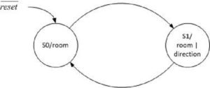
Technically, we will be implementing a Moore FSM. Which means that the output is completely defined by the current state and is independent of the inputs. As shown in Figure 2 on reset the FSM enters state S0 and only the room segments are displayed. On the next clock cycle the FSM unconditionally moves from state S0 to state S1. The term clock cycle is not the same as the 16Mz clock running the ATmega328P. Instead it is the software “clock” of our FSM. Specifically, one “clock cycle” is defined by the program looping back (rjmp loop) to the start of the loop section of code. Now, when the FSM enters state S1 both the room and direction segments are displayed. In this way, as the FSM continuously goes from state S0 to state S1 and then back again every 250 ms, the direction segment is turned on and then off – it “blinks.”
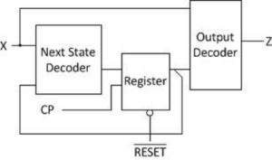
Following is a block diagram of our Moore FSM.
Here is how our FSM would translates into C++ (see Arduino Script Lab04A).
state = next_state;
switch (state){
state S0:
{
// output
seg7 = drawRoom(room);
// next state decoder
next_state = S1;
break;
}
state S1:
{
// output
seg7 = drawRoom(room) | drawDirection(dir);
// next state decoder
next_state = S0;
}
}
Notice that the Output decoder and Next state decoder blocks have equivalent software sections defined for each state. As Figure 1 illustrates and the code shows, the variable next_state is simply assigned to the other state in its corresponding “next state decoder” block of code. The output blocks of code also mimic their FSM state diagram counterparts.
In order to simplify how we represent the states, add the following two lines to the very beginning of the lab after the title block.
.EQU S0 = 0b00 // state 0
.EQU S1 = 0b01 // state 1
Where Do I Add My FSM?
Once completed your FSM will be replacing your current next_state logic and incorporating room and direction builder (DrawRoom, DrawDirection) within the output blocks of the FSM. Delete your simple blink logic done in the last section.
loop:
call ReadSwitches // read switches into r7
/* Read Switches and update room and direction */
// state = next_state;
lds r20, next_state // toggle next_state (prelab question 4)
:
sts next_state, r20
Incorporate this code into the output blocks of your FSM.
/* Room Builder */
lds r24, room // calling argument room is placed in r24.
rcall DrawRoom // translate room to 7 segment bits
mov spi7SEG, r24 // return value, the room, is saved to 7 …
call WriteDisplay // display the room
/* Draw Direction */
lds r24, dir // calling argument dir is placed in r24.
rcall DrawDirection // translate direction to 7 segment bit
mov spi7SEG, r24 // Display DrawDirection …
Block of code to update discrete LED variable spiLEDS
// writeDisplay(leds,seg7);
call WriteDisplay
rcall Delay // insert a delay of 250 ms
rjmp loop
Build Your FSM
Use the underlined code above with your FSM implementation. I have started the translation process from the C++ code to assembly to help you get started.
loop:
call ReadSwitches
// dir = switch & 0x03;
mov r17, switch // move switch (r6) to temporary register r17
cbr r17, 0xFC // mask-out most significant 6 bits
sts dir, r17 // save formatted value to SRAM variable dir.
/* Read Switches and update room and direction */
// room = switch >> 4;
mov r17, switch // move switch (r6) to temp register r17
cbr r17, 0x0F // mask-out least significant nibble
swap r17 // swap nibbles
sts room, r17 // save formatted value to SRAM variable room.
/* Moore FSM */
// state = next_state;
lds r20, next_state // r20 = current state
// switch (state)
// {
// state S0:
state_S0:
cpi r20, S0
brne state_S1
add your output and next state decoder
:
rjmp end_switch // break
state_S1:
cpi r20, S1
brne
add your output and next state decoder
:
rjmp end_switch // break
end_switch:
Block of code to update discrete LED variable spiLEDS
// writeDisplay(leds,seg7);
call WriteDisplay
rcall Delay // insert a delay of 250 ms
rjmp loop
When completed you should have only one call to WriteDisplay as shown here.
Upload and/or Simulate Your Completed FSM
Upload and/or simulate your completed FSM. Both discrete red LED 7 and direction LED of the 7 segment display should be blinking. The most significant 4 switches should be able to build a room as before.
So what should happen if the bear is headed into a wall? Specifically, the segment direction bit is also a wall segment bit in the room. In this instance, the 7-segment LED should always be ON (the bear cannot walk into a wall).
If you are still not sure how your program should behave, you can always open and upload the provided Arduino Script Lab04A.ino within the Arduino IDE.


