Lecture 2 – Robot Sensors and Actuators
System Engineering Your Robot
Table of Contents
Interfacing Sensors and Actuators
Reading
- Microcontroller Interfacing Circuits by Revolution Education Ltd.
- For help with a specific interface, or just to look for ideas, visit the related Arduino Forum.
- A detailed discussion of Pulse Width Modulation is beyond the scope of the document. We will be covering PWM in more detail later in the semester. For now you may want to read this nicely illustrated article: Working with Atmel AVR Microcontroller Basic Pulse Width Modulation (PWM) Peripheral
Introduction
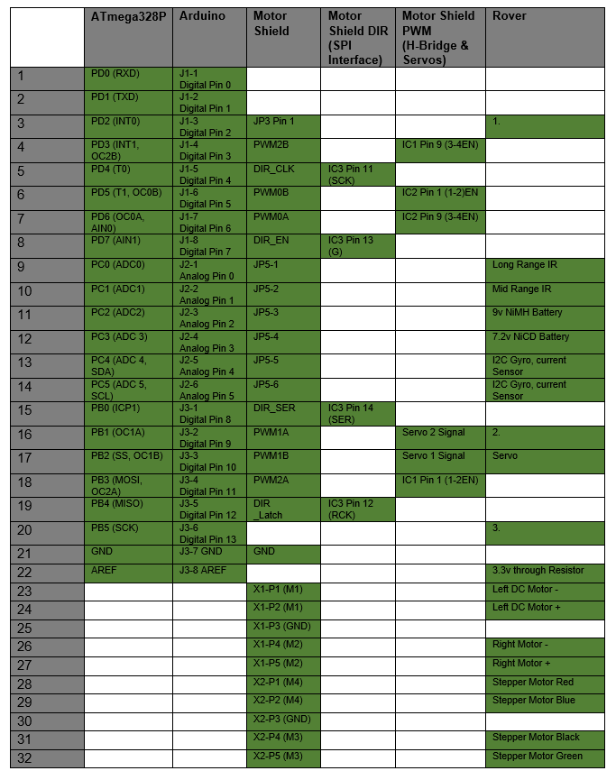
In Part 1 we developed a Resource Map for our rover (Table 1.0). In this section we look at how sensors and actuators could be incorporated into the design of our rover. Specifically, we will map our sensors and actuators to our I/O pins.
 Table 1.0 Rover Resource Summary
While Part 1 of this System Interface Design discussion was from the perspective of the ATmega328P; Part 2 will be presented from the perspective of the I/O device.
A detailed discussion of the ATmega328P subsystems, along with the software required to run them, is outside the scope of this document and will be covered in future lectures (hopefully).
Sensors
Digital Interface
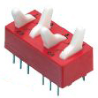
Design Example: DIP Switch
A DIP switch is an example of a digital sensor which you could add to your design. For example to allow your robot to discover its mode of operation upon reset.
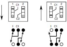
If you are not planning to implement the SPI interface and you do not have any Analog inputs, then working from the schematic of the device and the interface matrix, I would recommend wiring the four (4) Single Pole Double Throw (SPDT) DIP switch, shown in 1.0, to GPIO Pins (PF1, PB1, PB3, PB2, and PB1) of the ATmega32U4 or in Arduino parlance digital pins D22, D14, D16, D15. Button resources (Figure 2.1) would be allocated in a similar fashion.
Figure 1.0 Two SPDT DIP Switches
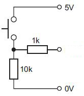
Figure 1.1 SPST Button Schematic
Parallel Interface
For our robots we are limited to no more than 9 digital inputs (see Section “3DoT Shields” in Part 1 of this series). Consequently, while wiring 1 button to the ATmega32U4 is not a problem, wiring a parallel device with a large word size is not directly possible. For example an 8-bit A/D converter would consume 89% of our available I/O resources. A much better solution would be an A/D converter that supports the I2C interface. Here we could get a 12-bit A/D converter with no loss in pin count.
Analog Interface
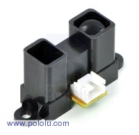
Many sensors output an analog voltage, including our IR sensors. The ATmega32U4 has a single ADC subsystem whose input can come from up to 6 multiplexed channels (ADC0 to ADC5). The reference design preserves all 6 of these analog channels. From a practical standpoint, the term multiplexed means that although our design can support up to 6 analog sensors, we can only read one at a time.
Design Example
As with all devices, start with a schematic
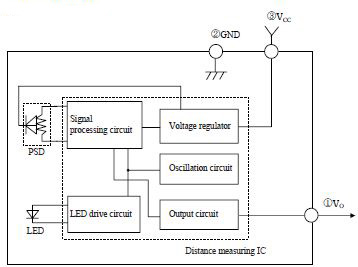
Figure 2.3 Medium Range IR Sensor Block Diagram
From the block diagram it is seen that the interface of an IR sensor is a single analog wire. In the absence of any other resource requirements, we are free to wire this sensor output to any one of our six analog inputs (ADC0 to ADC5).
Voltage Range and Electromagnetic Interference (EMI)
When working with any analog interface you should be sensitive to the output swing of the analog signal and to the introduction of noise.
For our medium range IR sensor, the Voltage Output peaks at around 3.1 V. That means to maximize our resolution we will want to use an external voltage reference of 3.3V. The full scale reading of the ADC can be set to the AVCC (5 v), AREF, or an internal 1.1v reference voltage. So in this case we will want to wire a 3.3v reference source to AREF. In a future lecture you will also find we need to place a limiting resistor between the our reference source and AREF.
Noise is almost always a concern when working with an analog signal. For our IR sensor the data sheet recommends a 10 uF capacitor be placed as closely as possible to the sensor. In addition, analog signals are often sent over a twisted and shielded cable.
Actuators
Digital Interface
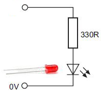
All ten available General Purpose I/O (GPIO) pins may be configured as outputs. The output circuit of the ATmega328 can sink or source a respectable 20 mA. This means that the ATmega328P can directly turn on/off LED indicators, without the need for an external driver (you will still need a limiting resistor).
Figure 3.0 Diode Circuit
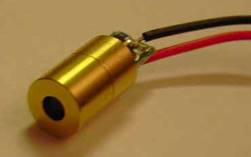
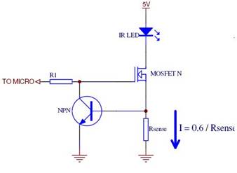
Another, digital actuator is our 650nm 1mW 8x13mm Laser Module. Once again before you purchase a device, make sure you have a datasheet. In the case of an laser, you need to know if it includes a current source, in which case you only need to turn the laser on/off, Otherwise, you will need to design in your own current source..
Figure 3.1 Laser Diode constant Current Circuit (source: Sparkfun Forum)
Motor and Pulse Width Modulation (PWM ) Interface
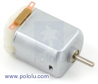
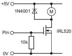
Motor On/Off
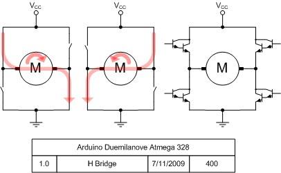
Change Motor Direction
Change the Speed of a Motor
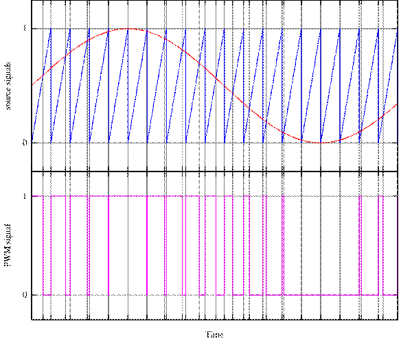
A simple variable resistor is all you need if you want to control the speed of a DC motor manually. To control the speed of a DC motor with a microcontroller you will use one of our six PWM channels (e.g., PWM1A, PWM1B).
Figure 3.4 A simple method to generate the PWM pulse train corresponding to a given signal is the intersective PWM: the signal (here the red sinewave) is compared with a sawtooth waveform (blue). When the latter is less than the former, the PWM signal (magenta) is in high state (1). Otherwise it is in the low state (0).: Wikipedia
All the Above
If you want to turn your DC motor on/off, change direction, and control the speed of the motor you will need two (2) GPIO pins to configure the H-Bridge and a single PWM channel to control the speed. Without the Adafruit motor shield, If you wanted to control 4 DC motors (or 2 DC motors and a Bi-polar stepper motor) you would need eight (8) GPIO pins plus 4 PWM channels. With the motor shield we only lost 4 GPIO pins – we still need 4 PWM channels.
Attaching a DC motor to the Adafruit motor shield is as simple as wiring your DC motor to one of the four (4) Motor control connector pairs.
Servos
Reprinted from : Microcontroller Interfacing Circuits by Revolution Education Ltd.
A typical servo has just three connection wires, normally red, black and white (or yellow). The red wire is the 5V supply, the black wire is the 0V supply, and the white (or yellow) wire is for the positioning signal. The positioning signal is a pulse between 0.75 and 2.25 milliseconds (ms) long, repeated about every 18 ms (so there are roughly 50 pulses per second). With a 0.75ms pulse the servo moves to one end of its range, and with a 2.25ms pulse the servo moves to the other. Therefore, with a 1.5 ms pulse, the servo will move to the central position. If the pulses are stopped the servo will move freely to any position. Unfortunately servos require a large current (up to 1A) and also introduce a large amount of noise on the power rail. Therefore as with all motors, the servo should be powered from a separate power supply. Remember that when using two power supplies the two ground rails must be joined to provide a common reference point.
Serial Interface
The ATmega328P supports three serial interface protocols: Universal Asynchronous Receiver/Transmitter (USART), Serial Peripheral Interface (SPI), and Inter-Integrated Circuit (I2C). All three support two-way communications. This means that all three serial subsystems of the ATmega328P can work as easily with actuators as sensors (see Section 2.1) which implement one or more of these interface types.
Universal Asynchronous Receiver/Transmitter (USART)
For the purposes of this study, the USART will be reserved for communications between the rover and the PC. As we learned in Part 1, the USART subsystem uses two IC pins (TXD and RXD).
Serial Peripheral Interface (SPI)
The SPI Subsystem of the ATmega328P requires four pins to implement 2-way serial communications (SCK, MISO, MOSI, SS). These lines are are wired to pins PB5 (SCK/PCINT5), PB4 (MISO/PCINT4), PB3 (MOSI/OC2A/PCINT3), and PB2 (SS/OC1B/PCINT2). Of interest here are Output Compare signals OC2A and OC1B. These signals are from the 8-bit Timer 2 and 16-bit Timer 1 subsystems. Both timer subsystems are used by the Adafruit motor shield to generate Pulse Width Modulated signals PWM2A and PWM1B. Pulse Width Modulation is critical for controlling the speed of DC motors (PWM2A) and setting the angle of a servo (PWM1B). Consequently, Adafruit implemented their SPI interface with General Purpose I/O (GPIO) ports and software. In this way they were able to maximize the number of PWM signals available to the shield, while sacrificing the SPI subsystem of the ATmega328P.
So what if you are working with a peripheral device that implements the SPI serial communications protocol? First, you can follow the Adafruit path and implement your SPI interface in software. Second, the SPI subsystem can be recovered at the cost of some functionality or the time sharing of shared resources. An example of the last case would be to communicate with your SPI device only when the shared motor control signal was not required (motor is off).
Inter-Integrated Circuit (I2C)
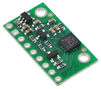
The I2C or TWI in Atmel speak, is a serial communications protocol with similar functionality to the SPI communications protocol. However, unlike the SPI which requires 4 pins to implement two-way communications, the I2C needs only two pins (SDA, SCL). The trade-off here is in the added complexity of the I2C interface. Today many intelligent sensors and actuators support both the I2C and SPI interface. This is the case with our L3G4200D 3-Axis Gyro Carrier with Voltage Regulator. As illustrated in Table 1.0 , the pins of the ATmega328P I2C subsystem are available for our sensors and actuators.
It should be noted that the I2C interface supports up to 128 devices without the need for any additional I/O pins.
Recovering I/O Resources
TBS
Rover Example
For our Rover we have the following Sensors and Actuators.
Sensors
I2C serial interface communicating with 3-Axis Gyroscope
I2C serial interface communicating with Current Sensor (optional)
I2C Arduino Nano (optional)
Analog input from Mid Range IR
Analog input from Long Range IR
Analog input from RC Circuit to 7.2V NiCD Battery – Dirty Power
Analog input from RC Circuit to 9V NiMH Battery – Clean Digital
Analog input from RC Circuit to 9V NiMH Battery – Camera
Four (4) Digital inputs from two (2) Shaft Encoders. Assumes full resolution of quadrature shaft encoders.
Actuators
Two (2) PWM outputs to H-Bridges controlling bipolar Stepper Motor – Adafruit Motorshield
Two (2) PWM outputs to H-Bridge controlling two DC Motors – Adafruit Motorshield
One PWM output to Servo – Adafruit Motorshield
One Digital output thru a Transistor circuit to turn the Laser on/off
One Digital output thru a Transistor circuit to turn the Camera on/off
(One or more Digital outputs to address bits of a 4051 Analog MUX for camera battery)
For our example we begin by allocating resources interfaced to ATmega328P peripheral subsystems requiring the use of only one set of pins. In this case the I2C serial interface. Looking at the matrix we see that this first step removes two Analog inputs leaving us with four (4). We need five (5) Analog Inputs so we are already in trouble. We will leave the sensors and actuators wired to the GPIO peripheral subsystem to the end. This is because these are the simplest to assign.The PWM channels are output from the Adafruit Motor Shield and so easily assigned. Once again we have very few options with respect to which pins can be used. We are now left with 4 Digital Input and 2 Digital Output pins to be connected to the GPIO peripheral subsystem of the ATmega328P. So we need to find 6 (4 inputs + 2 outputs) GPIO pins. Looking at the matrix we see that we have 3 GPIO pins left. So we are three (3) I/O pins short. How we find the 1 analog and 3 GPIO pins is left up to you. Hint: Look-up 4051, 74HCT595, and parallel shift registers like the 74HC166, 74HC194, and CD4014.
Rover with Arduino Nano Example
In this design example to the chassis mounted Arduino Uno we add a Arduino Nano to the scan/tilt platform.
Scan / Tilt Platform
Sensors
Analog input from Mid Range IR
Analog input from Long Range IR
Analog input from RC Circuit to 9V NiMH Battery – Camera
Actuators
One PWM output to Servo – Adafruit Motorshield
One Digital output thru a Transistor circuit to turn the Laser on/off
One Digital output thru a Transistor circuit to turn the Camera on/off
Serial Communication
For our example we begin by allocating resources interfaced to ATmega328P peripheral subsystems requiring the use of only one set of pins. In this case the I2C serial interface. Looking at the matrix we see that this first step removes two Analog inputs leaving us with four (4). We need two (2) Analog Inputs so we have two (2) pins which may be used for sensors and actuators to be wired to the GPIO peripheral subsystem (PC 2 – 5). Four (4) of our six (6) PWM channels are required by the Adafruit Motor Shield. This leaves us with two (2) more pins which may be used for sensors and actuators to be wired to the GPIO peripheral subsystem. Looking at the matrix we see that we have 2 GPIO pins PD2 and PB5 which are unused, giving us a total of six (6) pins available to the GPIO peripheral subsystem. We only need four (4) for our two shaft encoders which means we have two (2) spare pins.
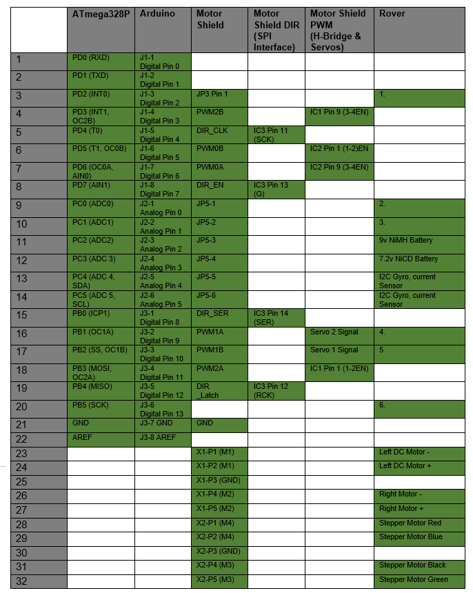 Table 3.0 System Resource Map for Chassis Mounted Arduino Uno

