Introduction to AVR Assembly Language Programming II: Branching
READING
The AVR Microcontroller and Embedded Systems using Assembly and C
by Muhammad Ali Mazidi, Sarmad Naimi, and Sepehr Naimi
Sections: 3.1
ADDITIONAL READING
Introduction to AVR assembler programming for beginners, controlling sequential execution of the program http://www.avr-asm-tutorial.net/avr_en/beginner/JUMP.html
Table of Contents
INSTRUCTION SET ARCHITECTURE (REVIEW)
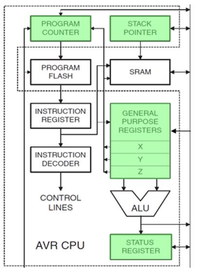
The Instruction Set Architecture (ISA) of a microprocessor includes all the registers that are accessible to the programmer. In other words, registers that can be modified by the instruction set of the processor. With respect to the AVR CPU illustrated here , these ISA registers include the 32 x 8-bit general purpose resisters, status resister (SREG), the stack pointer (SP), and the program counter (PC).
Data Transfer instructions are used to load and store data to the General Purpose Registers, also known as the Register File. Exceptions are the push and pop instructions which modify the Stack Pointer. By definition these instructions do not modify the status register (SREG).
Arithmetic and Logic Instructions plus Bit and Bit-Test Instructions use the ALU to operate on the data contained in the general purpose registers. Flags contained in the status register (SREG) provide important information concerning the results of these operations. For example, if you are adding two signed numbers together, you will want to know if the answer is correct. The state of the overflow flag (OV) bit within SREG gives you the answer to this question (1 = error, 0 no error).
Control Transfer Instructions allow you to change the contents of the PC either conditionally or unconditionally. Continuing our example if an error results from adding two signed numbers together we may want to conditionally (OV = 1) branch to an error handling routine. As the AVR processor fetches and executes instructions it automatically increments the program counter (PC) so it always points at the next instruction to be executed.
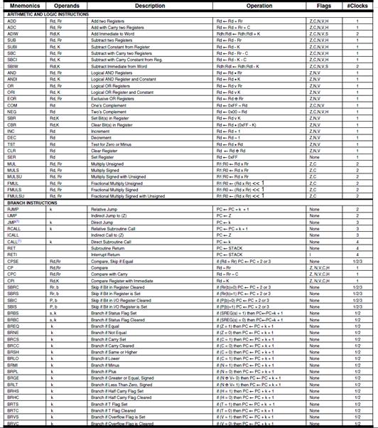
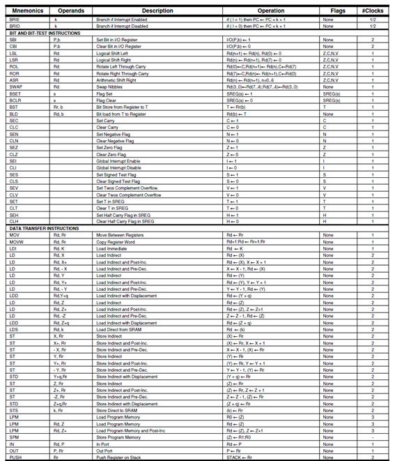
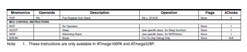
INSTRUCTION SET (REVIEW)
The Instruction Set of our AVR processor can be functionally divided (or classified) into the following parts:
- Data Transfer Instructions
- Arithmetic and Logic Instructions
- Bit and Bit-Test Instructions
- Control Transfer (Branch) Instructions
- MCU Control Instructions
JUMP INSTRUCTIONS
- There are two basic types of control transfer instructions – Unconditional and Conditional.
- From a programmer’s perspective an unconditional or jump instruction, jumps to the label specified. For example, jmp loop will unconditionally jump to the label loop in your program.
- Here are the unconditional control transfer “Jump” instructions of the AVR processor
Direct jmp, call Relative (1) rjmp, rcall Indirect ijmp, icall Subroutine & Interrupt Return ret, reti
Note:
- Jump relative to PC + (
, where k = 12)
PC-2048 to PC+2047, within 16 K word address space of ATmega328P
HOW THE DIRECT UNCONDITIONAL CONTROL TRANSFER INSTRUCTIONS JMP AND CALL WORK
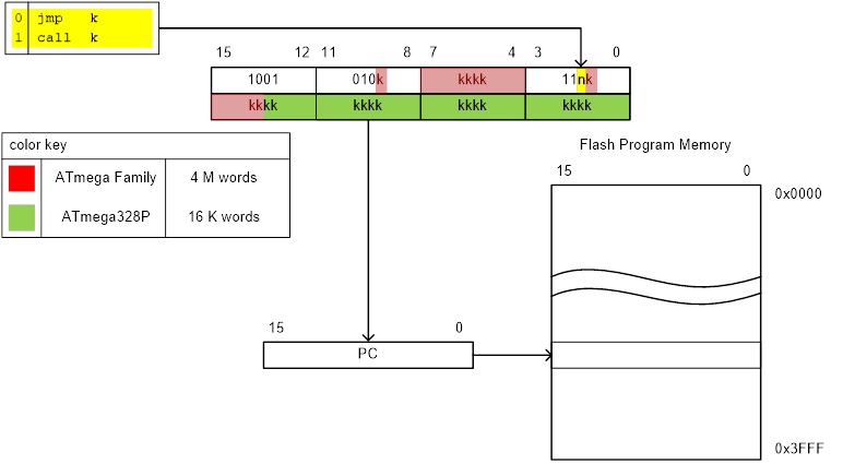
- From a computer engineer’s perspective, a direct jump is accomplished by loading the target address into the program counter (PC). In the example, the target address is equated to label “loop.”
- To provide a more concrete example, assume the label loop corresponds to address 0x0123 in Flash Program Memory.
- To execute this instruction, the control logic of central procession unit (CPU) loads the 16-bit Program Counter (PC) register with 0x123.
- Consequently, on the next fetch cycle it is the instruction at location 0x0123 that is fetched and then executed. Control of the program has been transferred to this address.
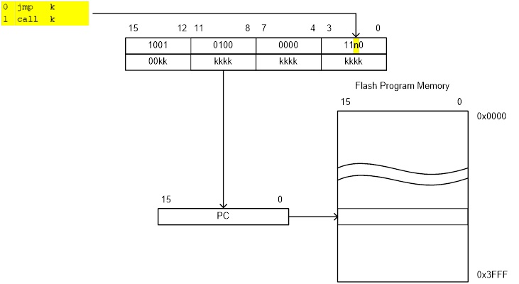
Figure 2: JMP & CALL Machine Code Stored in Flash Program Memory
HOW THE RELATIVE UNCONDITIONAL CONTROL TRANSFER INSTRUCTIONS RJMP AND RCALL WORK
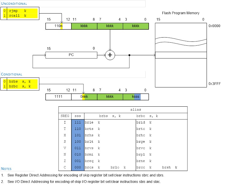
- From a computer engineer’s perspective, a relative jump is accomplished by adding a 12-bit signed offset to the program counter (PC) . The result corresponding to the target address. In the example, the target address is equated to label “loop.”
- To provide a more concrete example, assume the label loop corresponds to address 0x0123 in Flash Program Memory (the target address).
- An rjmp loop instruction is located at address 0x206. When the rjmp is executed, the PC is currently fetching what it thinks is the next instruction to be executed at address 0x207.
- To accomplish this jump the relative address (kkkk kkkk kkkk) is equal to 0xF1C (i.e., 0x123 – 0x207).
- Consequently, on the next fetch cycle it is the instruction at location 0x0123 that is fetched and then executed. Control of the program has been transferred to this address.
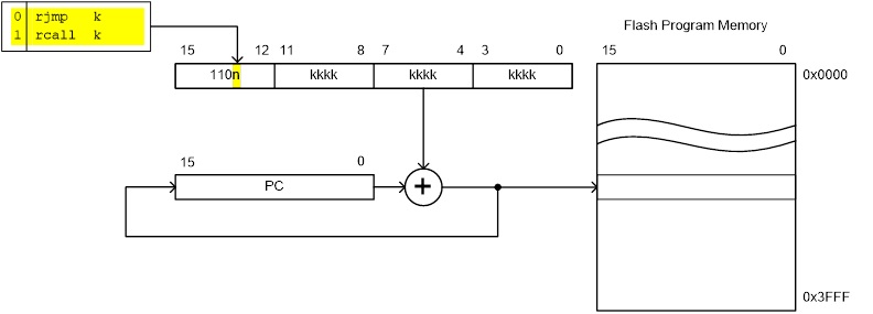
Figure 3: RJMP & RCALL Machine Code Stored in Flash Program Memory
BRANCH INSTRUCTIONS
- When a conditional or branch instruction is executed one of two things may happen.
- If the test condition is true then the branch will be taken (see jump instructions).
- If the test condition is false then nothing happens (see nop instruction).
Note: This statement is not entirely accurate. Because the program counter always points to the next instruction to be executed, during the execution state, doing nothing means fetching the next instruction.
- The “test condition” is a function of one SREG flag bit. For example, the branch if equal (breq) or not equal (brne) instructions test the Z flag.
HOW THE RELATIVE CONDITIONAL CONTROL TRANSFER INSTRUCTION BREQ WORKS
- If a relative branch is taken (test condition is true) a 7-bit signed offset is added to the PC. The result corresponding to the target address. In the example, the target address is equated to label “match.”
- To provide a more concrete example, assume the label nomatch corresponds to address 0x0123 in Flash Program Memory (the target address).
- A brne nomatch instruction is located at address 0x0112. When the brne instruction is executed, the PC is currently fetching what it thinks is the next instruction to be executed at address 0x0113.
- To accomplish this jump the relative address (kk kkkk) is equal to 0b01_0000 (i.e., 0x123 – 0x113).
- Consequently, on the next fetch cycle it is the instruction at location 0x0123 that is fetched and then executed. Control of the program has been transferred to this address.
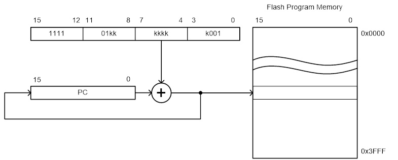
Figure 4: Branch Changes Position of Pointer Counter
BRANCH INSTRUCTIONS
- All conditional branch instructions may be implemented as brbs s,k or brbc s,k, where s is the bit number of the SREG flag bit. For example brbs 6, bitset would branch to label bitset, if the SREG T bit was set.
- To make your code more readable, the AVR assembler adds the following “alias” instructions.
- SREG Flag bit is clear (brFlagc) or set (brFlags) by name (I, T, H, S, V, N, Z, C) or bit (brbc, brbs).
- These SREG flag bits (I, T, H, S, V, N, Z, C) use more descriptive mnemonics.
- Branch if equal (breq) or not equal (brne) test the Z flag.
- Unsigned arithmetic branch if plus (brpl) or minus (brmi) test the N flag, while branch if same or higher (brsh) or lower (brlo), test the C flag and are equivalent to brcc and brcs respectively.
- Signed 2’s complement arithmetic branch if number is less than zero (brlt) or greater than or equal to zero (brge) test the S flag
Skip if …
- Bit (b) in a register is clear (sbrc) or set (sbrs).
- Bit (b) in I/O register is clear (sbic) or set (sbis). Limited to I/O addresses 0-31
Note:
- All branch instructions are relative to PC + (
, where k = 7) + 1
- Skip instructions may take 1, 2, or 3 cycles depending if the skip is not taken, and the number of Flash program memory words in the instruction to be skipped (1 or 2).
CONDITIONAL BRANCH ENCODING
Here is how the brbs, brbc and their alias assembly instructions are encoded.
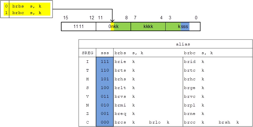
Figure 6: Branching Machine Code
A CONDITIONAL CONTROL TRANSFER (BRANCH) SEQUENCE
A conditional control transfer (branch) sequence is typically comprised of two (2) instructions.
1. The first instruction performs some arithmetic or logic operation using the ALU of the processor.
- Examples of this first type of instruction includes: cp, cpc, cpi, tst
- These ALU operations result in SREG flag bits 5 to 0 being set or cleared (i.e., H, S, V, N, Z, C).
- To allow for multiple branch conditions to be tested, these instructions typically do not modify any of our 32 general purpose registers.
- The compare instructions cp, cpc, cpi should be used when you want to understand the relationship between two registers. For compare instructions, this is accomplished by performing a subtraction operation without a destination operand (cp r16,r17 is equivalent to r16 – r17).
- The tst instruction should be used when you want to test if the number in one register is negative or zero. For a test instruction, this is accomplished by performing an and operation with the destination and source registers being the same (tst r16 is equivalent to and r16,r16).
WARNING: The Atmel “Instruction Set Summary” document incorrectly classifies compare instructions (cp, cpc, cpi) as “Branch Instructions.” They should be listed under “Arithmetic and Logical Instructions.” To highlight this inconsistency on Atmel’s part, the tst instruction is correctly listed under “Arithmetic and Logical Instructions.”
2. The second instruction is a conditional branch instruction testing one or more SREG flag bits.
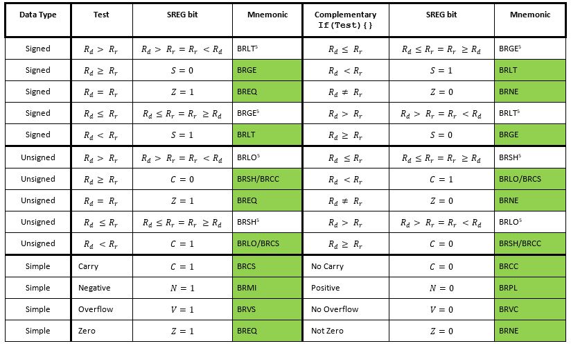
CONDITIONAL BRANCH INSTRUCTION SUMMARY
As mentioned in the previous slide, typically a conditional control transfer instruction follows a compare or test instruction, where some relationship between two registers is being studied. The following table may be used to quickly find the correct conditional branch instructions for these conditions.
A Conditional Control Transfer (Branch) Example
Here is how a high-level language decision diamond would be implemented in assembly.
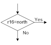
Figure 7: If Branch Flow Chart
; directions (see note)
.EQU south=0b00 ; most significant 6 bits zero
.EQU east=0b01
.EQU west=0b10
.EQU north=0b11
cpi r16,north ; step 1: Z flag set if r16 = 0b00000011
breq yes ; step 2: branch if Z flag is set
Note: These equates are included in testbench.inc
IMPLEMENTING A HIGH-LEVEL IF STATEMENT
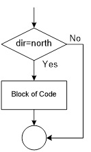
Figure 8: High-level If Branch Flow Chart
- A high-level if statement is typically comprised of…
- Conditional control transfer sequence (last slide) where the complement (not) of the high-level conditional expression is implemented.
- High-level procedural block of code is converted to assembly.
- C++ High-level IF Expression
if (r16 == north) {
block of code to be executed if answer is yes.
} - Assembly Version
cpi r16,north ; Is bear facing north?
brne no ; branch if Z flag is clear (not equal)
block of code to be executed if answer is yes.
no:
IMPLEMENTING A HIGH-LEVEL IF…ELSE STATEMENT
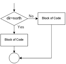
Figure 9: If-else Branch Flow Chart
- A high-level if…else statement is typically comprised of…
- Conditional control transfer sequence where the complement (not) of the high-level conditional expression is implemented.
- High-level procedural block of code for yes (true) condition.
- Unconditional jump over the no (false) block of code.
- High-level procedural block of code for no (false) condition.
- C++ High-level if…else Expression
if (r16 == north) {
block of code to be executed if answer is yes (true).
}
else {
block of code to be executed if answer is no (false).
} - Assembly Version
cpi r16,north ; Is bear facing north?
brne else ; branch if Z flag is clear (not equal)
block of code to be executed if answer is yes.
rjmp end_if
else:
block of code to be executed if answer is no.
end_if:
ASSEMBLY OPTIMIZATION OF A HIGH-LEVEL IF…ELSE STATEMENT – ADVANCED TOPIC –
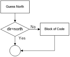
Figure 10: If-else Flow Chart
- If the if-else blocks of code can be done in a single line of assembly then the program flow is modified to guess the most likely outcome of the test.
- This is possible if the value of a variable (for example the segments of a 7-segment display to be turned on) is the only thing done in each block.
- This optimized program flow will always execute as fast as the normal if..else program flow (if the guess if wrong) and faster if the guess is correct.
- This implementation is also more compact and often easier to understand.
- Assembly Version

; 7-segment display (see note)
.EQU seg_a=0
.EQU seg_b=1
.EQU seg_c=2
…
ldi r17,1<
cpi r16, north ; Is bear facing north?
breq done
clear (not equal)
block of code to be executed if guess was wrong.
done:
Note: These equates are included in spi_shield.inc
Program Examples: Group A or B – Pseudocode example
- Objective
Assign the least significant 4 switches on the CSULB shield to group A and the most significant to group B. Based on user input, display A or B based on which group has the higher value. In the event of a tie display E for equal. For this programming problem assume that people choose A 50% of the time, B 40% of the time, and set the switches equal to each other 10% of the time.
- Pseudocode
- Using the ReadSwitches subroutine or reading the I/O ports directly, input group A into register A (.DEF regA = r16) and group B into register B (.DEF regB = r17)
- Preload the output register (.DEF answer = r18) with the letter A
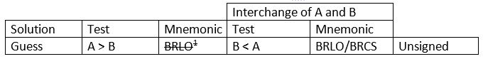
Guess
- If (A>B) then go to display answer.
- Preload the output register with the letter B
- If (B>A) then go to display answer.
- Set answer to E and display answer.
- Seven segment display values.
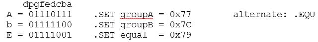
- Programming work around by interchanging Rd and Rr.
Direction Finder – Two Program Solutions
- Objective
Design a digital circuit with two (2) switches that will turn on one of the rooms 4 LED segments indicating the direction you want your bear to walk
- Direction to Segment Conversion Table
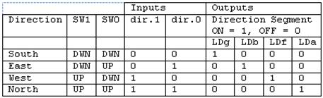
- Programmer’s Reference Card

Direction Finder – Truth Table Implementation
 lds r16, dir // move direction bits into a working register

 // facing east (segment b)
 bst r16,0   // store direction bit 0 into T
 bld var_B,0 // load r16 bit 0 from T
 bst r16,1   // store direction bit 1 into T
 bld var_A,0 // load r17 bit 0 from T
 com var_A   // B = /A * B
 and var_B, var_A
 bst var_B,0 // store r16 bit 0 into T
 bld spi7SEG, seg_b // load r8 bit 1 from T

Implementation of Boolean expressions for segments a, f, and g (circuit schematic)
Direction Finder – Using Conditional Expressions
lds r16, dir
ldi r17, 1< cpi r16,south ; if bear is facing south then we are done
breq done
ldi r17, 1< cpi r16,west ; if bear is facing west then we are done
breq done
ldi r17, 1< cpi r16,east ; if bear is facing east then we are done
breq done
ldi r17, 1<
done:
mov spi7SEG, r17 ; answer to 7-segment register
call WriteDisplay
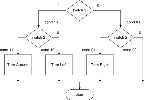
Pseudo-Instructions TurnLeft, TurnRight, and TurnAround
Using switches 3 and 2, located on Port C pins 3 and 2 respectively, input an action you want the bear to take. The three possible actions are do nothing, turnLeft, turnRight, and turnAround. Write a subroutine named WhichWay to take the correct action as defined by the following table.
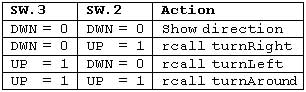
Table 5.2: Truth Table of Turn Indicators
; ————————–
; — Which Way Do I Go? —
call ReadSwitches // input port C pins (0x06) into register r7
bst switch, 3 // store switch bit 3 into T
brts cond_1X // branch if T is set
bst switch, 2 // store switch bit 2 into T
brts cond_01 // branch if T is set
cond_00:
rjmp whichEnd
cond_01:
rcall TurnRight
rjmp whichEnd
cond_1X:
// branch based on the state of switch bit 2
:
cond_10:
:
cond_11:
:
whichEnd:
Warning: The above code is for illustrative purposes only and would typically be found in the main looping section of code not in a subroutine. Do not use this code to implement your lab.
InForest and Implementation of IF…ELSE Expression
- The inForest subroutine tells us if the bear is in the forest (i.e., has found his way out of the maze).
- The rows and columns of the maze are numbered from 0 to 19 (13h) starting in the upper left hand corner.
- When the bear has found his way out of the maze he is in row minus one (-1). The subroutine is to return true (r25:r24 != 0) if the bear is in the forest and false (r25:r24 == 0) otherwise.
- The register pair r25:r24 is where C++ looks for return values for the BYTE data type.
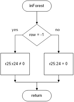
Figure 16: inForest Flow Chart
InForest and Implementation of IF…ELSE Expression – Continued –
; ————————–
; ——- In Forest ——–
; Called from whichWay subroutine
; Input: row Outputs: C++ return register (r24)
; No others registers or flags are modified by this subroutine
inForest:
push reg_F // push any flags or registers modified
in reg_F,SREG
push r16
lds r16,row
test if bear is in the forest
endForest:
clr r25 // zero extend
pop r16 // pop any flags or registers placed on the stack
out SREG,reg_F
pop reg_F
ret
Appendix
APPENDIX A: CONTROL TRANSFER INSTRUCTION ENCODING
Direct
All control transfer addressing modes modify the program counter.
JMP & CALL Machine Code Stored in Flash Program Memory
CONTROL TRANSFER INSTRUCTION ENCODING – Indirect
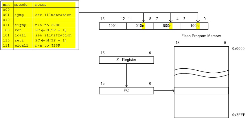
Indirect Instructions Machine Code
CONTROL TRANSFER INSTRUCTION ENCODING – Relative
Relative Branching Machine Code Stored in Flash Program Memory
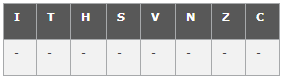
APPENDIX B – AVR STATUS REGISTER (SREG)
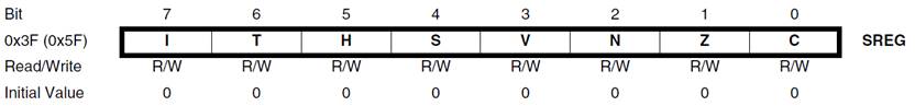
Status Register
Non ALU
- Bit 7 – I: Global Interrupt Enable
The Global Interrupt Enable bit must be set for the interrupts to be enabled. The individual interrupt enable control is then performed in separate control registers. The I-bit is cleared by hardware after an interrupt has occurred, and is set by the reti instruction. The I-bit can also be set and cleared by the application with the sei and cli instructions. - Bit 6 – T: Bit Copy Storage
The Bit Copy instructions bld (Bit LoaD) and bst (Bit STore) use the T-bit as source or destination. A bit from a register can be copied into T (RbT) by the bst instruction, and a bit in T can be copied into a bit in a register (T
ALU
Signed two’s complement arithmetic
- Bit 4 – S: Sign Bit, S = N ⊕ V
Bit set if answer is negative with no errors or if both numbers were negative and error occurred, zero otherwise. - Bit 3 – V: Two’s Complement Overflow Flag
Bit set if error occurred as the result of an arithmetic operation, zero otherwise. - Bit 2 – N: Negative Flag
Bit set if result is negative, zero otherwise.
Unsigned arithmetic
- Bit 5 – H: Half Carry Flag
Carry from least significant nibble to most significant nibble. Half Carry is useful in BCD arithmetic. - Bit 0 – C: Carry Flag
The Carry Flag C indicates a carry in an arithmetic operation. Bit set if error occurred as the result of an unsigned arithmetic operation, zero otherwise.
Arithmetic and Logical
- Bit 1 – Z: Zero Flag
The Zero Flag Z indicates a zero result in an arithmetic or logic operation.
APPENDIX C – CONTROL TRANSFER (BRANCH) INSTRUCTIONS
Compare and Test cp, cpc, cpi, tst, bst
Unconditional
- Relative (1) rjmp, rcall
- Direct jmp, call
- Indirect ijmp, icall
- Subr. & Inter. Return ret, reti
Conditional
- Branch if (2) …
- SREG Flag bit is clear (brFlagc) or set (brFlags) by name (I, T, H, S, V, N, Z, C) or bit (brbc, brbs).
- These SREG flag bits (I, T, H, S, V, N, Z, C) use more descriptive mnemonics.
- Branch if equal (breq) or not equal (brne) test the Z flag.
- Unsigned arithmetic branch if plus (brpl) or minus (brmi) test the N flag, while branch if same or higher (brsh) or lower (brlo), test the C flag and are equivalent to brcc and brcs respectively.
- Signed 2’s complement arithmetic branch if number is less than zero (brlt) or greater than or equal to zero (brge) test the S flag
- Skip if …
- Bit (b) in a register is clear (sbrc) or set (sbrs).
- Bit (b) in I/O register is clear (sbic) or set (sbis). Limited to I/O addresses 0-31
Note:
- Branch relative to PC + (
, where k = 12) + 1
- All branch relative to PC + (
APPENDIX D – ATMEGA328P INSTRUCTION SET