Chassis/Fall 2018/PCB Design
By Cristian Figueroa & Larry Vinh
Table of Contents
Introduction
With the previous generation’s PCB short circuiting, we’re tasked with redesigning it. While looking at it, it was discovered that there were some things that were questionable in their design. We had problems with connectors; specifically, the wires were easily removed from the connectors with little effort. The way the motor drivers were placed, they would make contact with the PCB and potentially cause a short. Finally, their board was a little too big with a lot of excess space so we tried to minimize that.
Design Of PCB
One of the design faults of the previous design was the placement of the motor drivers on the PCB. The previous layout was prone to being shorted by the motor drivers, which is why the previous generation put a rubber substance on the bottom of them to combat that. When redesigning the board, we kept that in mind and the solution we came up with is adding a second PCB, just for the motor drivers, that mounts vertically on the main PCB. The way it works is the motor drivers get slid into card guides that are mounted on the main PCB to hold them in place where they are connected to the second PCB. We had to put the components that were in the middle of the old PCB on the bottom of our design in order to be able to slide in the motor drivers without anything getting in the way. Special consideration was taken with the height of the second PCB so that it would not hit the lid of the Box of the Chassis. There is a 2.5″ clearance from the PCB to the lid and the second PCB has a height of 1.625″ so there’s around an inch of free space between the lid and the electronics.
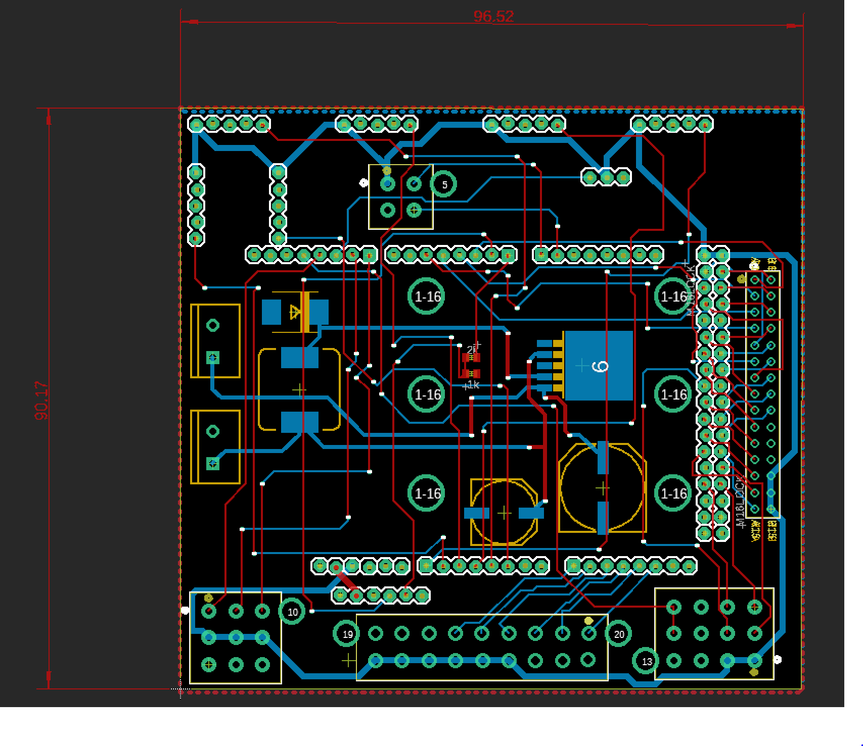
Figure 1: PCB For Motor Shield
Another design fault was with the connectors that they used where the wires were coming to on the PCB. Since the connectors had no way of keeping the wires in them, if a small amount of force was applied on the connectors the wires would come out. We decide to use housing connectors to eliminate that problem which had many pluses in making the connections easy for anybody to do. The basics of how it works is that all the wires get crimped and then put into a plug in for the receptacle on the board. The housing has a latch so once it’s plugged in it won’t come off unless unlatched. Another benefit was that it was keyed which meant that there is only one way to connect the plug so that eliminates any confusion on what should be plugged in and where. Anybody should be able to plug in the plug without knowing anything about the electronics, hence being user friendly.
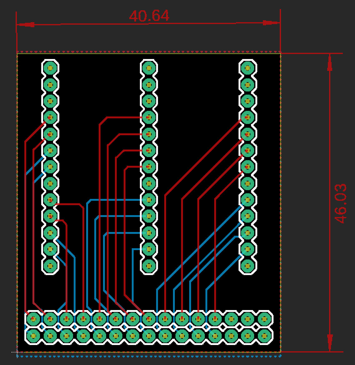
Figure 2: PCB For Chassis
Other than the connectors, the motor drivers shields, and the more efficient placement of the components on the PCB, nothing else was changed. The previous design had around a 5’’x 3’’ board and we have around a 3.80”x3.55″ design. This was done to try and make the board smaller and more cost-efficient, since there is less empty space.
Connectors
by: Larry Vinh
The main change to make the PCB more user friendly for future generations was the connectors. Previously, the PCB had a lot of wires going into female connectors. This was problematic because it was difficult to figure out which wires go into which connectors. The solution to this was to change the connectors to polarized housing connectors.
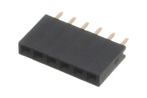
Figure 3: 6 pin female connector
The connector that will only be used for breakout boards on the main PCB. This changed from having wires connected to female connectors as well.
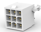
Figure 4: Polarized housing connector
This is the new type of connector that will be used for the wires instead of female connectors.
The first image is a straight pin female connector that we will be replacing. The second image is a polarized housing connector that will replace most of the female connectors on the PCB. Three of the edges on the polarized connectors are shaped as pentagons rather than rectangles. As a result, these connectors can only be connected in one orientation. We grouped the wiring for parts that have similar or the same properties together, so it will be easier for future generations to identify. For example, the Ultrasonic sensors and the LEDs for them were grouped into the 3×4 connector. Another thing that was changed about the connectors were the dimensions. The downside about the new polarized connectors is that they are significantly larger then the straight pin connectors. It results in the PCB requiring more space than anticipated.
Conclusion
The addition of a second PCB should avoid potential short-circuits to the main PCB for the Chassis. The inclusion of slots to the motor driver PCB will allow for air circulation to prevent the motor drivers from overheating. The polarizing connectors will make it easier to connect everything from the Chassis to the PCB. This will make the Chassis easier to start-up for future generations. The following generations will be able to figure out the connections quickly. All the changes done to the PCB will allow future generations to avoid past errors and make further improvements to the Chassis.