Goliath Generation 5 Summary Blog Post
Author/s: Felix Velasquez and Josephine Tjandra
Table of Contents
Executive Summary
The Goliath Robot is based on the Goliath 302 Tank from World War II. We will be creating an indestructible, force of nature designed to track hills and rugged terrain. The Goliath, with its unique and interesting model, will be at the forefront of all robots. The purpose of this document is to provide a summary of the Goliath Fall 2018 Project. This document will provide useful links and resources of all the major tasks performed this semester as well as major tasks that were used from previous semesters.
Program and Project Objectives
Program Objectives
The Robot Company (TRC) will be debuting its 2019 line-up of toy robots and associated games at the Toy-Invasion 2019 convention in Burbank CA on January 6, 2019. Your team’s assignment is to make the 3D printed and/or laser-cut prototypes to be showcased at the convention, prior to production starting in the second quarter of 2019. The robots will feature our new ArxRobot smart phone application and the Arxterra internet applications allowing children to interact and play games around the world. In addition, the robots should be able operate autonomously in game mode. See game(s) (i.e, mission objectives) assigned to your robot by the Game Division. To decrease electronics cost, interoperability between all TRC robots will be maintained by incorporation of the 3DoT board, developed by our Electronics R&D Section. Modification of downloadable content is limited to software switch setting and robot unique graphics of the smart phone and Arxterra applications. Modifications of electronics is limited to custom 3DoT shields as required by the unique project objectives of your robot. The Marketing Division has set our target demographic as children between the ages of 7 and 13, with a median (target) age of 11. To decrease production costs, please keep robots as small as possible, consistent with our other objectives. As with all our products, all safety, environmental, and other applicable standards shall be met. Remember, all children, including the disabled are our most important stakeholders. Our Manufacturing Division has also asked me to remind you that Manufacturability and Repairability best practices must be followed.
Project Objectives
The TRC Goliath project will offer an opportunity to study the limitations of a robot over a realistic terrain. A Goliath robot offers increased maneuverability and improved stability over traditional tanks. Its small size and light weight feature allows it to be well suited for young kids while also being sturdy. Its tracked-wheel system will allow the tank to traverse around rugged terrain. Its integration with an Android phone using the Arxterra App and open-sourced control boards allows for future builders to easily recreate or improve on the Goliath design.
Mission Profile
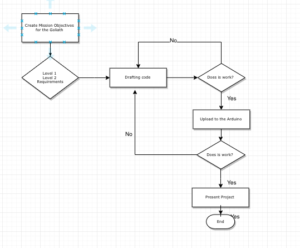
The goal of Fall 2018 Goliath is to improve on the Goliath 302 tank design from Fall 2016. The Mission is to navigate a 2-D paper/cloth maze under remote control through the Arxterra App and have the Goliath repeat the route autonomously.
Project Features
Requirements
Based on the customer’s expectations and the mission objectives, we have come up with various Level 1 Requirements that are quantitative, verifiable, and realizable. This allows us to move the design process forward and obtain a clear understanding of what we are trying to accomplish.
Engineering Standards and Constraints
We are in compliance with constraints on the project imposed by The Robot Company (i.e., CSULB) and Project Stakeholders. Specifically, we include University and applicable environmental, health, and safety standards and those safety standards specifically associated with the product (e.g., Children’s Toys).
Applicable Engineering Standards
- IEEE 29148-2018 – ISO/IEC/IEEE Approved Draft International Standard – Systems and Software Engineering — Life Cycle Processes –Requirements Engineering.
- NASA/SP-2007-6105 Rev1 – Systems Engineering Handbook
- Bluetooth Special Interest Group (SIG) Standard (supersedes IEEE 802.15.1)
- C++ standard (ISO/IEC 14882:1998)
- Federal Communications Commission (FCC) Relevant standards for a product implementing a 2.4GHz radio, FCC Intentional Radiators (Radio) Part 15C, and Unintentional Radiators FCC Part 15B for CPU, memories etc.
- NXP Semiconductor, UM10204, I2C-bus specification and user manual.
- ATmega16U4/ATmega32U4, 8-bit Microcontroller with 16/32K bytes of ISP Flash and USB Controller datasheet section datasheet, Section 18, USART.
- USB 2.0 Specification released on April 27, 2000, usb_20_20180904.zip
- Motorola’s SPI Block Guide V03.06
Environmental, Health, and Safety (EH&S) Standards
CSULB College of Engineering (COE) Safety Resources. Start your search for applicable CSULB COE Safety Standards and Procedures here. Please review and acknowledge if any safety issues as defined by the COE applicable to your project. For example, the closest safety constraint for a linear actuator is for use of the Hydraulic Press located in the Engineering Technology (ET) Building Lab. Here is a link to the Hydraulic Press Safety document.
CSULB Environmental Health & Safety (EH&S)
IEEE National Electrical Safety Code (NESC)
NCEES Fundamental Handbook (FE) Reference Handbook
ASTM F963-17, The Standard Consumer Safety Specification for Toy Safety, is a comprehensive standard addressing numerous hazards that have been identified with toys. In 2008, the Consumer Product Safety Improvement Act of 2008 (CPSIA) mandated that the voluntary toy safety standard in effect at that time become a nationwide mandatory children’s product safety rule.
Disposal of Hazardous Waste including Electronic and Solar Cells
CSULB Physical Planning & Facilities Management (PPFM) Environmental Compliance Electronic Waste Handling and Disposal Procedures. These procedures shall be followed for the disposal of all batteries.
Program Level 1 Requirements
Project/Economic
Subcategories: Cost, Extensibility, Interoperability, Maintainability, Quality, Marketability, and Schedule
All 3DoT robots shall be constrained to a not to be exceed Cost of $250.
All project Schedules shall be constrained to a completion date of Tuesday December 18, 2018. Project completion includes documentation and materials purchased by or loaned to the project.
One of the Economic Factors affecting our robots are return rates. To demonstrate the durability and child friendliness of our robot a simple drop test from 1.4 meter shall be performed. The height is defined by the average height of an average 11 year old girl.
Extensibility is designed into the 3DoT board by way of one 8-pin 100 mil connector located on the front of the board and two 8-pin 100 mil connectors located on the top of the board. By plugging shields into these connectors, the 3DoT board can support a diverse set of robots. All robots shall contain one or more custom designed 3DoT shields. The 3DoT shield(s) incorporating interface electronics between the 3DoT board and sensors and/or actuators unique to the robot. Surface Mount Technology (SMT) will be employed unless a waiver for through-hole parts is granted.
Maintainability: Disassemble and Reassemble of the robot shall be constrained to less than 20 minutes (10 + 10 minutes). Disassembly: The 3Dot board is clear of all other electronic and mechanical subassemblies. All electronic and mechanical subassemblies and associated connectors, sensors, and actuators including motors are disconnected. A functional test of the robot is conducted after reassembly to confirm its functionality. All project may reference a cable tree as well as an assembly diagram as necessary. This requirement is demonstrated/verified on the last day of the schedule. Projects may request a waiver with justification.
Social and Ethical
Subcategories: Accessibility, Aesthetics, and Usability
Accessibility by the blind and Marketability of the robots shall be implemented/enhanced by a speaker. The speaker shall generate sound effect consistent with the type of the robot. For example, the Goliath tank would make “track” sounds, the AT-ST sound effects would mimic their Star Wars antecedent.
Wiring Aesthetics shall be nice and clean with the usage of terminal blocks, 100 mil contact pins and headers, 2.0mm PH series JST connectors, and barrel connectors. Handling Precaution for Terminal and Connector will be in compliance with JST documentation.
To enhance Aesthetics, the robot shall be designed in such a way that there are no dangling or exposed wires. Connectors will used between all electronic and electromechanical components. Jumper wires will not be used, ribbon cables are preferred.
To enhance Aesthetics, the form factor of a robot modeled on a real or fictitious robot shall be constrained by the original. For example, Goliath should be a scale model of the real Goliath 302 tank. Projects may request a waiver with justification.
Usability of the robots shall be enhanced by adding autonomous functions and/or by use of the Arxterra phone application as dictated by the assigned mission.
Manufacturability
Subcategories: Constructability, Size, Weight, and Power (SWAP)
Constructability of 3DoT robots shall be documented at the CDR and approved by the president of the TRC robot company. Constraints imposed by this requirement include the use of bushing or bearings in all moving and rotating parts. Interlocking Hinges with latching mechanism. No gaps greater than 1 millimeter, and immediate access to all external connectors (USB, switches).
Manufacturability of 3D printed robots shall be demonstrated by compliance with the 3/3/3 rule. Specifically, total print of a robot is constrained to 9 hours, with no single print taking longer than 3 hours. Projects may request a waiver with justification.
The Size of the electronics enclosure, shall be constrained to be no greater than the 3DoT board, 3DoT shield(s), and associated mounting hardware.
Power to all 3D robots shall be provided by the 3.7V RCR123A battery included with the 3DoT board or use of the external battery 2.0mm PH series JST connector located on the 3DoT board. The RCR123A is a Lithium Polymer LiPo battery. All Safety regulations as defined in Section 4.3 Hazards and Failure Analysis of this document shall apply to the shipping, handling, storage, and disposal of LiPo batteries.
Back of the envelope calculations and experiments shall be conducted to set the diameter of Power carrying wires. Follow the American Wire Gauge (AWG) standard when defining the diameter of power carrying wires. This work to be completed and documented by the CDR.
Environmental Health and Safety (EH&S) Standards
Subcategories: Environmental Standards, Sustainability, Toxic waste (Solar panels), Health and Safety, Ergonomics
All standards, codes, and regulations as defined in the “Engineering Standards and Constraints” Section of this document shall apply.
Functional
All 3DoT robots shall incorporate the 3DoT v7 series of boards.
Software shall be written in the Arduino De facto Standard scripting language and/or using the GCC C++ programming language, which is implements the ISO C++ standard (ISO/IEC 14882:1998) published in 1998, and the 2011 and 2014 revisions. Required exceptions to this standard can be found here.
All 3DoT robots shall be in compliance with the 3DoT Command and Telemetry Packet specification.
All 3DoT robots shall be controlled via Bluetooth 4.0 in compliance with the Bluetooth Special Interest Group (SIG) Standard (supersedes IEEE 802.15.1).
Project Level 1 Functional Requirements
The Level 1 Functional Requirements describe the functions and characteristics that Goliath will have.
L1-1 Schedule – Project shall be completed by Tuesday, December 18th, 2018
L1-2 Operational Task – Goliath shall be responsive to user input commands from and send data to the ArxRobot mobile App
L1-3 Maintainability: Disassemble and Reassemble the robot shall be less than 20 minutes (10 + 10 minutes).
L1-4 Driving Surface – Should autonomously traverse shortest path of maze
L1-5 Driving Surface – The Goliath shall traverse on cloth, paper and linoleum
L1-6 Print Time – Total print time is less than 9 hours, with no single print taking longer than 3 hours
L1-7 3Dot – The Goliath should use the 3Dot Board
L1-8 Appearance – The Goliath shall appear in scale to the real Goliath 302 tank
L1-9 Functional – Goliath should be responsive to user input commands and sends telemetry to Arxterra
L1-10 Budget – The total cost of the Goliath shall remain under $250
L1-11 Funcitonal – The Goliath shall traverse a maze under remote control
L1-12 Functional – The Goliath should remember the manual instructions given for navigating the maze
L1-13 Aesthetics – Should have access to USB Port without tools
L1-14 Functional – The Goliath shall remain operating for at least 0.5 hours
L1-15 Aesthetics – The Goliath shall be smaller by volume than the previous version
L1-16 Economic Factors – Goliath should withstand impact of wall and other robots
L1-17 Power: Power to all 3Dot robots should be provided by the 3.7 volts RCR123A battery included with the 3Dot board
L1-18 Functional: The Goliath should be controlled via bluetooth
System/Subsystem/Specifications Level 2 Requirements
The Level 2 Requirements are derived from the Level 1 Requirements. Based on a specific requirement, we came up with a Level 2 Requirement to meet the original requirement.
L2-1 Mechanical/Manufacturing –Based on L1-15, the mass of the Goliath shall not exceed 350 grams
L2-2 Electronics – Based on L1-17, the voltage drawn from the 3DOT should not exceed 3.6V
L2-3 Mechanical/Manufacturing – Based on L1-16, the Goliath should withstand impact of wall and other robots
L2-4 Electronics– Based on L1-17, the total current drawn from the 3DOT should not exceed 650mA
L2-5 Safety and Quality Assurance – Based on L1-3, the wires in Goliath shall be clean with no bare wire showing and wires tied together
L2-6 Mechanical/Manufacturing – Based on L1-15, the Goliath will be smaller than 4.71x 3.77 x1.8 inches (Fall 2016 size)
L2-7 Safety and Quality Assurance– Based on L1-16, the Goliath should withstand a drop test from 1.4 meters.
L2-8 Mechanical/Manufacturing – Based on L1-8, The Goliath should not exceed 20% of the original scaling factor
Electronic Subsystem Requirements
- Magnetic Sensor – The Goliath shall utilize a Magnetic Sensor to detect the path in order to navigate the maze.
- Magnetometer Sensor – Power – The Goliath’s Magnetic sensor shall not draw consume more 4.4 mA at than 3.3V.
- Gyroscope-Power – The Goliath’s Gyroscope shall not use consume more than 3.2mA at 3.3V.
- Gyroscope-Tracking – The Goliath shall utilize a gyroscope to make turns within the maze.
Manufacturing Subsystem Requirements
- Goliath-Size Change – The Goliath shall measure 4.71×3.3×1.8 (LxWxH)
- Wire Routing – Wires should be maintained on a clear path (away from the center)
- Durability – At max acceleration, force shall not exceed F<<350*a
- Component placement – Mass of Goliath will be evenly distributed (front to back)
- Component placement – The Goliath shall have two gears in the side panels
Allocated Requirements / System Resource Reports
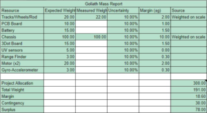
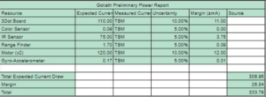
Allocated requirements, also known as resource reports, are written and tracked by the System Engineer. Each resource has a margin attached to it based on the uncertainty in the estimate. We also show contingency, where contingency is defined as the project allocation minus the estimate plus total margin.
Mass Resource Report / Allocation
Power Resource Report / Allocation
Project Report
In this section we will discuss our work breakdown structure and our product breakdown structure. We will mention our schedule for the semester as well as the products that we ended up purchasing and their costs to use for the Goliath F’18.
Project WBS and PBS
Project Work Breakdown Structure (WBS) and Product Breakdown Structure (PBS).
References:
- Chapter 4, section 3 of the NASA Systems Engineering Handbook titled “Logical Decomposition” includes a section that briefly covers the Product Breakdown Structure (PBS.) Chapter 6, section 1 titled “Technical Planning” includes a section that explains the relationship between the Work Breakdown Structure (WBS) and the PBS. The PBS is the responsibility of the systems engineer. There is not quite enough information between these two sections to create a long presentation; instead focus on first going over the info, and then work with your division members to create an example PBS during the meeting.
- NASA SE Handbook Sections 4.2, 4.3-2, 6.1-4/5,G-1
- Arxterra / Classes / Engineering Method, select “class lecture” tab, scroll down to The Robot Company Work Breakdown Schedule.
- WBS and PBS PowerPoint by Avi Sharma
Cost
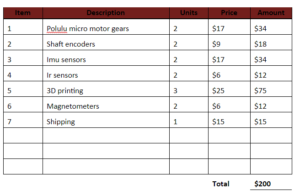
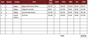
For the Goliath 3Dot Robot this fall 2018 semester the team researched the necessary parts that we would be using to build the Goliath 302 tank. Below in the figure we can see the parts that we initially anticipated for this semesters project.
Towards the end of the semester, the team reached the conclusion that not all goals would be reached, and therefore reduced the Total cost of the Goliath Robot.
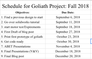
Schedule
On our schedule, we were able to complete our motor testing to determine which motors we would be using as well as modifying the SolidWorks for the new gear system and new motor placement. At the time that the project was due, we had just finished up the 3D models on SolidWorks and had it printed. Unfortunately, the set up of the gear system was not what the customer wanted but we were out of time. We would say that we got around 70% of the work done, and it was the final implementation and design that we were not able to complete.
Concept and Preliminary Design
For the Goliath 302 tank of Fall 2018, the team decided to go with the design from Generation #2 for an initial starting point. From here, the team created new mission objectives for our robot, and from there decided on what new design features we needed to implement.
Literature Review
The first step toward reaching our objectives was to start from previous Goliath projects. We researched the previous generations through the Arxterra website to find a design that would be a good starting point. Once the team had the design, we needed to see how it needed to modify it in order to meet the level 1 and level 2 requirements. Using Solidworks, the team was able to achieve some of the new design changes like reducing the size of the Goliath, moving the motors to a new location, as well as a new bevel gear system. For the electronics part of the project, the team conducted multiple experiments ranging from calculating the amount of current drawn from the motors to finding out the different specifications of each motor. For the Firmware of the robot, the team used the Arduino Uno board to run code to make prototypes of the Goliath to move. Example of code could be found on the Arxterra website from previous generations. Overall, these were the different approaches the team made in order to reach our final mission statement.
Design Innovation
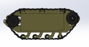
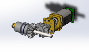
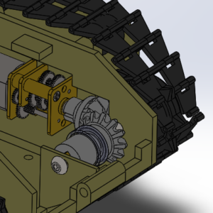
For this semester’s Goliath redesign, our main points of focus was to make the Goliath smaller, move the motors to the compartments in the side panels resulting in a new gear system being added, create a better latching system for the top and bottom panel, figure out a better way to attach the small rotating wheels, and add ribbing to increase the structural strength of the Goliath top and bottom panels. Shown below is the new bevel gear system we added to facilitate moving the motors to the side panels. To see more of the redesign and the changes we made, refer to the Goliath Fall 2018- Redesign blog post.
Conceptual Design / Proposed Solution
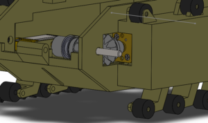
Our main project specifications was to move the motors of the Goliath into the already open space in the side panels. The proposed solution for moving the motors and not having them connect directly to the drive wheel anymore was a new gear system that was introduced above. This will allow the motor to sit in the side panels and allow us to remove excess space from the body which will then result in the Goliath fitting the 3Dot board tightly. This will result in a smaller volume of a Goliath that maximizes the space. The other components of the Goliath stayed relatively similar to past generations and not much was changed. The Goliath’s mission of navigating a maze through remote control through the Arxterra app and then navigating the path autonomously was the same as previous semesters. Our preliminary budget for the Goliath was around $350 including the sensors, 3D printing, and motors. We would like to have the Goliath completed by Tuesday, December 18, 2018.
System Design / Final Design and Results
For this semester’s Goliath redesign, our main points of focus was to make the Goliath smaller, move the motors to the compartments in the side panels resulting in a new gear system being added, create a better latching system for the top and bottom panel, figure out a better way to attach the small rotating wheels, and add ribbing to increase the structural strength of the Goliath top and bottom panels.
Manufacturing Final Design
Our conceptual design included the motor being moved to the side panels. In the final design, we were not able to create a pocket for the motor and had to makeshift a pocket with foam. The motor successfully connected to the gear system and ran, but due to some manufacturing issues, we had to connect both sides of the gear system with a single shaft which was not what the customer wanted. The final design also was not as small as the customer had expected it to be. It was only modified in its width and not the length which is what the customer had anticipated being modified.
Electronics Final Design
With the team being limited to two people, the electronics portion of the Goliath did not meet the expectations that the team had originally thought. A prototype of the Goliath was 3D printed and could move to some extent via bluetooth commands. Unfortunately, the App that was used was not to Professors Hill’s liking, which he later expressed his feelings about it to the electronics team (although when presented to the ABET people, they actually liked it). Furthermore, the team also wanted to create a PCB design to make a clean wiring for sensors like the IR/Magnetometers sensors and the Gyro sensors. This plan was not met over this semester’s Goliath Project.
System Block Diagram
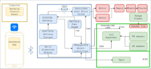
This is the previous semester S’18 block diagram. We were ideally attempting to implement the same system and product. The system block diagram illustrates how components of the Goliath communicate and connect with each other; from the control panel that uses Wi-Fi to talk with the mobile app to the wheels and treads. More detailed specific components such as the HM11 Bluetooth model is added, and various parts on the PCB parts are laid out.
Modeling/Experimental Results
References:
- Arxterra / Classes / Engineering Method, select “class lectures” tab, scroll down to Design Process and Modeling.
- IEEE Guide for Developing System Requirements Specifications
For this Generation of the Goliath, DC motor Experiments were done to motors already obtained from previous Generations. The experiments helped conclude which DC motors would be ideal for our Goliath Robot to reach our mission objectives. Here is a link to those Experimental Results.
Mission Command and Control
3DoT Robots
This section provides a systems level look at the software modules employed by 3DoT robots. This section represents a collaborative effort by the system and electronics/control engineers.
| Hardware | Software |
| Personal Computer | Arxterra Control Panel |
| Smartphone | ArxRobot App |
| 3DoT Board | Arduino and Robot3DoT Library |
Electronic Design
Going into the project, there are some programs that one need to be familiar with in order to do well with the project. The Arduino scripting language is one of the programs that is used to control the tank; while Eagle CAD is another program that is used to design a custom PCB.
For the electronic components, one of the main components in this robot was the DC motors that are going to be used to move the Goliath. The experiments done during the semester was to determine how much current would be drawn from the each motor and whether or not that would be enough to move the Goliath or if it would be too much current that it might fry the board. Another electrical aspect of this project was the sensors that were meant to be used. A embedded systems class had worked on code for the IR sensors that could have been adapted to our Goliath tank.
PCB Design
This is section shows the progression of the design from Fritzing diagram (optional), to physical breadboard photo, to PCB schematic, PCB layout, and finally a photo of the completed board; preferable integrated with the product itself.
The PCB design of this semesters Goliath was not created. The initial objective was to incorporate a mode on the Goliath to navigate the 2D maze using a magnetometer or IR sensor to follow the path.
Firmware
In order to complete the main goal of this mission, app directed control to the Goliath was needed. This comprehensive guide talks about how setting up custom commands all the way down to how the major whichway decision making within the maze is effected. This guide defines the general case used by all bots, but the code represented is the Goliath version.
Here is a link a previous Generations Code that was used this semester in order to use the App to send commands to the robot.
Mechanical/Hardware Design
The google drive file linked above contains all the SolidWorks files for the F’18 Goliath, including the new gear system given by Jeff Gomes. The design was based on the Gen 2 Goliath models and were modified accordingly. The main components to notice are the new gear system and how it sits in the body.
Verification & Validation Test Plan
Reading and Resources:
- Arxterra / Getting Started / Systems Engineering / Missions, Systems and Test Timeline
- Week #7 – Product Verification & Firmware Setup
- Week #8 – Product Validation & Cable Tree/Cable Routing Diagram
- Sample Verification and Validation Plans
The Verification and Validation Test Plan verifies that our design meets design requirements and how we will validate that we built the right product for the mission.
 Loading...
Concluding Thoughts and Future Work
RESEARCH, RESEARCH, RESEARCH. At the start research as much as you can about the past project your building on (start at this document). Then read through all the posts from that semester. Lots of work has already been done and just uncovering it and reading may take time but, it is worth it.
Provide your group with some goal every week. This will help keep your project on task and helps the members remain focused on their independent tasks. Planing this isn’t easy but, as project manager just form a general goal and then ask everyone how to get there.
Get a Prototype working ASAP. The main reason is to have time for programming model iterations and so on. Without this, there is no code to write and the code will take the longest!
Start Coding EARLY. The programming work can be long and tiresome. Most programming takes hours troubleshooting per feature. Starting early gives the highest chance of success.
PCB Design has a long Verification time. Designing a PCB is the easy part, getting it approved, then assembled and working is the hard part.
Plan to iterate the 3D model at least 5 times. Get a 3D model designed (even if it is rough) and just get it printed. Each time you print it, there will be something to improve or fix that was not thought of. Plus by the time you get to the end the timeline, 3D printing and assembly will be easier. If you don’t know Solidworks find someone who does.
References/Resources
These are the starting resource files for the next generation of robots. All documentation shall be uploaded, linked to, and archived in to the Arxterra Google Drive. The “Resource” section includes links to the following material.

