Preliminary Design Review
By: Pathfinder Generation 7
Christopher Fingers (Design and Manufacturing)
Daniel Enverga (Mission, System, and Testing)
Patrik Hertle (Electronics and Control)
Alexandrea Jackson (Project Manager)
Table of Contents
Program Objective
The Pathfinder Generation 7 team will work together to create a functional robot for The Robot Company within 15 weeks (May 13th, 2019). The pathfinder will use the Arxterra Control Panel as the main interface to communicate using bluetooth.
Project Objective
Maneuver over a simulated Mars terrain encountered on the CSULB campus predetermined by Pathfinder Generation 5. Communicate to and from pathfinder using Arxterra Control Panel and mobile device. Designed to be aesthetically similar to the NASA mars pathfinder using a rocker bogie system. The main objective of this Pathfinder generation is to make the rover functional once again. Completion of the Pathfinder Generation 7 by May 13th, 2019.
Mission Profile
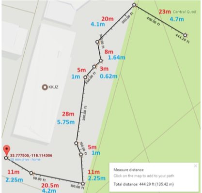
The Spring of 2019 Pathfinder will follow the path laid down by previous Pathfinder Generation 5. The mission will begin in front of the CSULB library. The rover will then proceed to begin its journey through campus, a 0.09 mile journey to 10 checkpoints already predefined. The 10 GPS checkpoints along the way and the rover will traverse a flight of stairs.
Requirements
These requirements include level 1 and level 2 that link to level 1 requirements. These will be updated at a later post. Level 1 requirements should be more functional while level 2 should be performance.
Level 1
1.1 Pathfinder shall navigate through CSULB course as defined by Pathfinder Generation 5.
1.2 Pathfinder shall be able to maneuver through Mars simulated terrain as encountered on CSULB course using a Rocker-Bogie system.
1.3 Pathfinder shall be powered using rechargeable battery that will be interfaced with Solar Array team.
1.4 Users shall view terrain through the Arxterra Control panel with a mobile camera on pan and tilt system.
1.5 Pathfinder shall update users on telemetry of chassis through Arxterra Control panel.
1.6 Pathfinder shall avoid objects (larger than TBD) during course completion.
1.7 Pathfinder shall be aesthetically similar to Mars Rover with improvements to be functional maneuvering through CSULB course as defined in the mission profile.
1.8 Pathfinder Chassis shall be integrated with solar array via customized PCB and Arduino.
1.9 Pathfinder shall be completed by Monday, May 13th, 2019 as defined by course outline.
Level 2
2.1.1: The pathfinder shall travel a 0.09 mile course defined by Pathfinder 5. This course includes going up a set of 3 stairs at a 45 degree incline and decline as determined by the course in Figure 1.
2.2.1: Motors shall operate at and provide a torque of TBD Nm and TBD rpm allowing obstacles to move through stairs as defined in the CSULB course.
2.2.2: Pathfinder shall use a differential gear-box system to stabilize and level the chassis.
2.3.1:The Pathfinder’s 12 volt rechargeable battery shall be able to provide 5.7 amps of current for the Arduino Atmega, ultrasonic sensors, the 6 dc motors, a stepper motor and 2 servos.
2.3.2: A battery charger should be installed to connect the solar panel and the pathfinder battery.
2.4.1: Servos shall operate at X V to aid with the pan and tilt system for horizontal and vertical direction.
2.4.2: The Pathfinder shall be 14.25” by 9.25” and .25” thick as predetermined by Pathfinder generation 5 for stability center of gravity purposes.
2.4.3: A Pan and Tilt mechanism shall be mounted on top of the Pathfinder for mobile device to be mounted for use of camera viewing.
2.5.1: Arxterra Control Panel shall update users via Bluetooth on GPS location, battery levels.
2.5.2: Shaft/Rotary encoders shall be used to determine the speed of the wheels to update users through arterra control panel app.
2.5.3: Pathfinder shall switch in manual mode to be controlled by control panel when object (larger than 5 inches) is detected.
2.5.4: The user shall be able to control pathfinder via Arxterra Control Panel when switched to manual mode.
2.5.5: Watchdog timer should shutdown or stop to prevent malfunctions due to loss of communication.
2.6.1:Pathfinder shall use ultrasonic sensors to detect obstacles ranging from 3cm to 2m away.
2.6.1: A 6-wheel electronic differential shall be implemented as defined in Pathfinder 5 to increase power to other motors is current of motors is too high.
2.6.2: The slip differential should be implemented to better overcome obstacles if time permits.
2.6.3:Pathfinder should determine height of obstacles using ultrasonic sensor to overcome obstacle or not.
2.7.1: The wiring for the Pathfinder Chassis should be more aesthetically pleasing. This can include using wire grouping items and/or increase the size of the chassis.
2.7.2: The pathfinder should include insulation to prevent shorts and damage to the electronics due to aluminum body.
2.8.1: The custom PCB shall integrate motorshields, encoders, motors ultrasonic, serovos, motor, bluetooth, etc.
2.8.2: The pathfinder shall integrate will solar providing TBD amount of pins on Arduino.
2.8.3: The pathfinder should be enclosed with Solar Array mounted on enclosement.
2.9.1: the Pathfinder shall complete the CSULB course by Monday May 13th, 2019 as defined by course syllabus.
Product Breakdown Structure
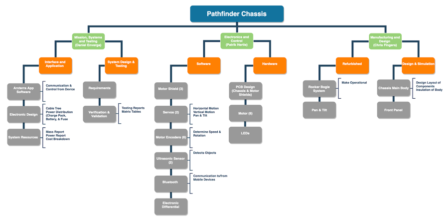
Figure 1: Product Breakdown Structure
Software Design
By: Patrik Hertle
Our E&C included a UML of our code. At first Patrik created his own commands, but changed them after the PDR to include the Arxterra Library found in the Getting Started. The software design will be explained in a later post.
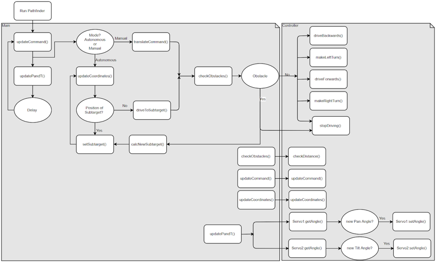
Figure 2: Software Block Diagram
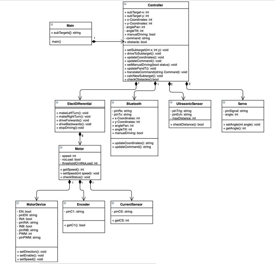
Figure 3: UML Block Diagram
System Block Diagram
By: Daniel Enverga
Improvements to the System Block Diagram include more detail such as how many wires will be used, encoders should be added, etc.
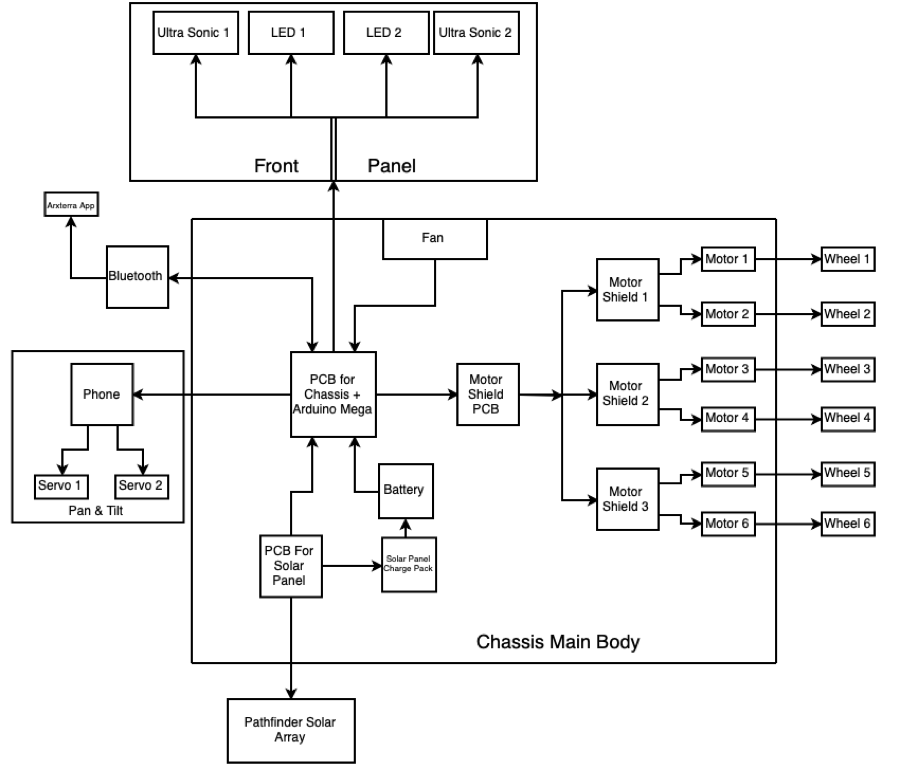
Figure 4: System Block Diagram
Interface Matrix
By: Daniel Enverga
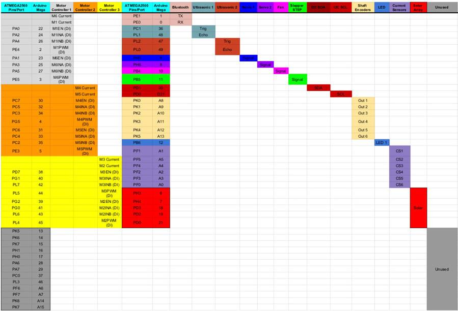
Figure 5: Interface Matrix
Mechanical Design
By: Chris Fingers
This semester’s main goal is to bring back the Pathfinder to a functional level, therefore the current iteration of the pathfinder, as shown in figure 1, will be the design used. The design changes for this semester will be aimed at internal insulation, PCB redesign and protection for the differential.
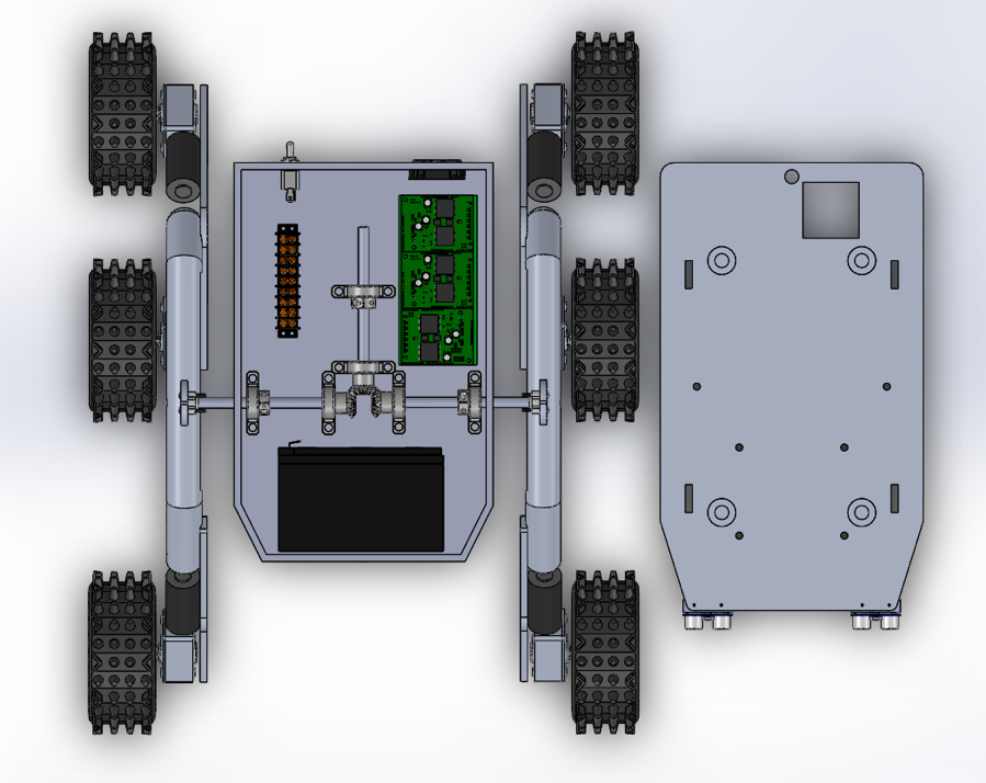
Figure 6: Chassis inside as provided by Generation 5
Problem:
The differential gear box and the rocker bogie system for the Pathfinder have no been tested since generation 4 due to the conductive nature of the aluminum body. This caused a problem when a lead was dropped, which shorted out the electrical equipment.
Insulation:
The aluminum casing of the pathfinder is both a blessing and a curse. The frame for the robot is sturdy and relatively lighter than other types of materials, however short-circuiting problems can and have occurred. A solution for this problem would be to line the inside of the chassis with PVC foam. This will prevent any loose leads or wires coming into contact with the aluminum body. Also, for added protection, the Arduino mega 2560 should be placed inside a plastic container. This will help with the insulation of the Pathfinder and protect the Arduino from any minor bumps.
PCB design:
The current PCB design for the motor shield is slightly off from connecting with the 3 motor drivers. A new PCB will need to be designed by shifting the pin inputs to the right by 5/16th of an inch. The pin inputs that connects the motor shield to the main PCB board will have the input pins soldered behind the motor shield instead of in front of it.
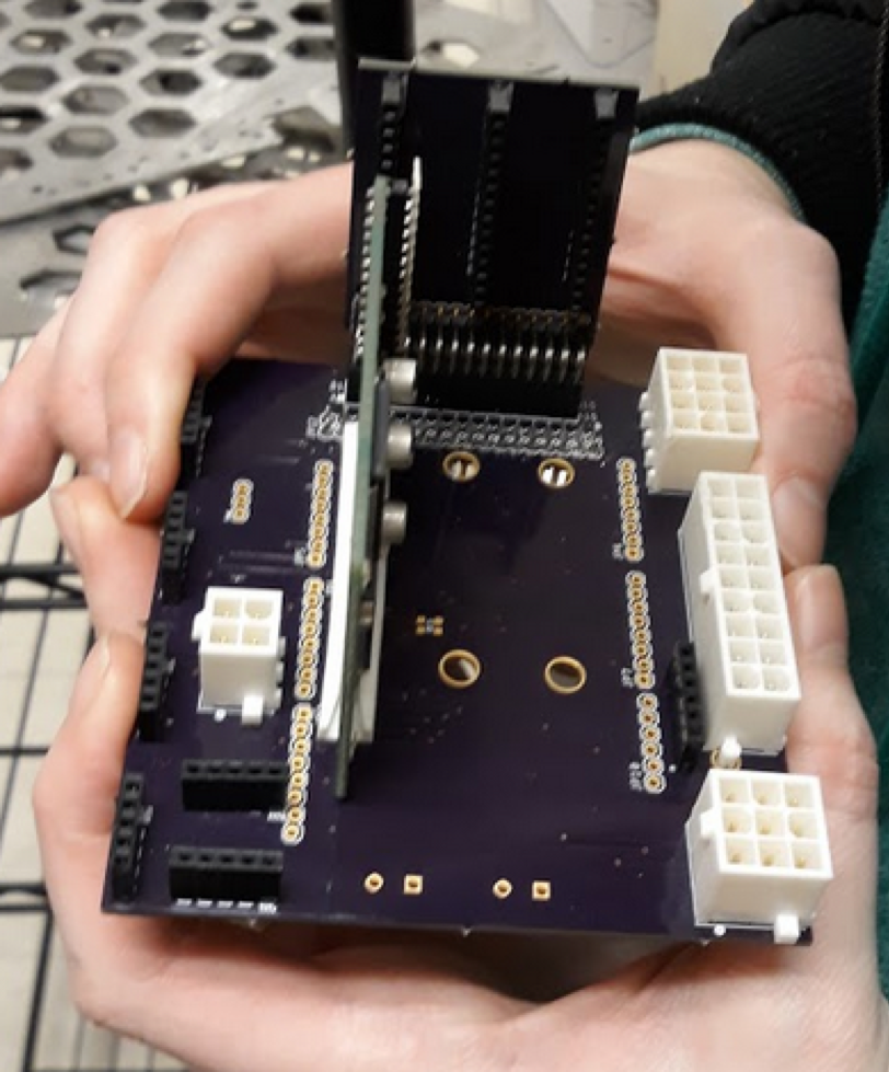
Figure 7: Generation 6 PCB
Rocker Bogie System:
Proper testing for the rocker bogie system needs to be performed to have a better understanding of problem areas. With the last proper test being that of generation 4, and the differential gear box installed in generation 5, problem areas need to be identified. Grommets will be installed between the chassis and the differential gear pole that is connected to the wheels. Differential diameter, is 0.19 inches with the connecting hole in the body of the chassis at 1.0 inches with a .25 in thickness in the body of the chassis.
Preliminary Project Plan
By: Alex Jackson
Schedule
For the project schedule, TargetProcess was used to capture this timeline. This was a brief timeline of the current and planned tasks. More tasks were updated after the PDR as necessary.
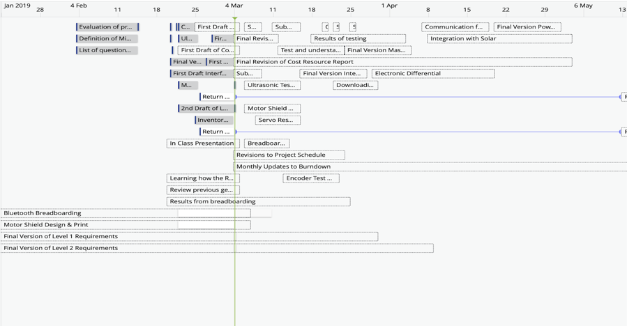
Figure 8: Project Schedule
Work Breakdown Structure
By: Alex Jackson
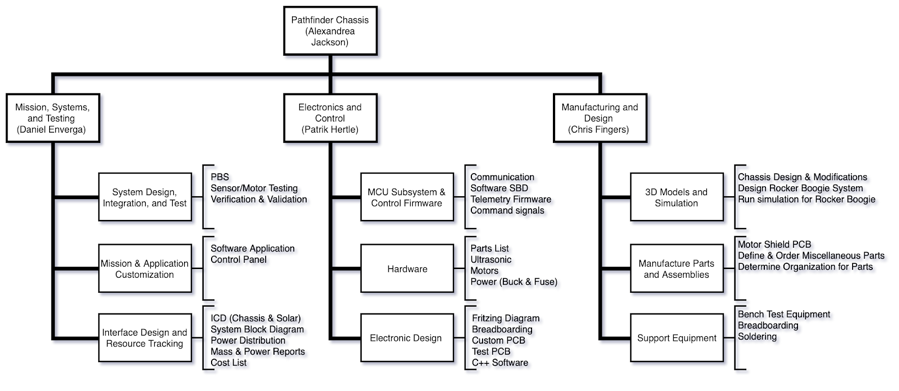
Figure 9: Work Breakdown Structure
System Source Reports
By: Daniel Enverga
Our system source reports are generated below, but will be updated in a later post with the correct margins and contingency along with our estimated values.
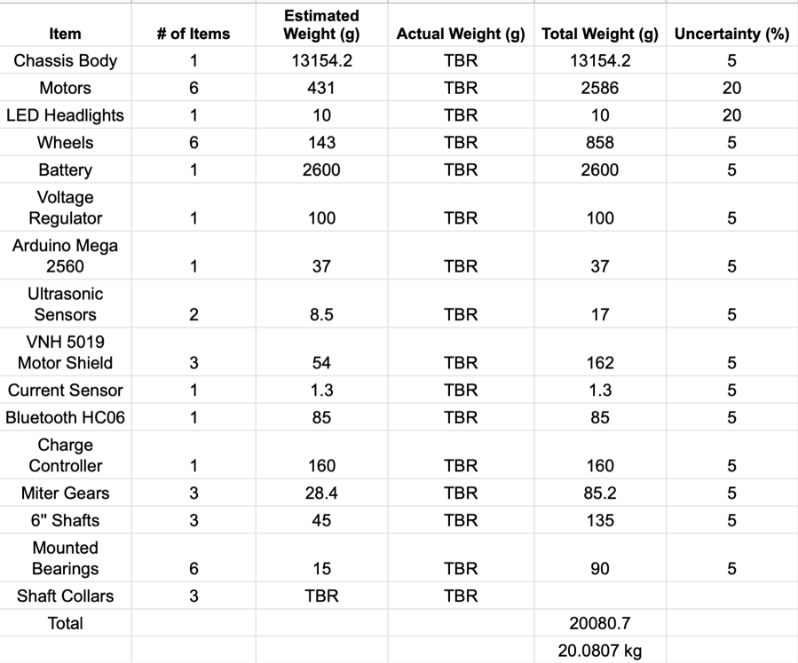
Figure 10: Mass Shared Report
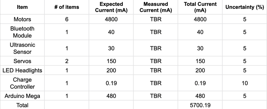
Figure 11: Power Shared Report
Cost Report
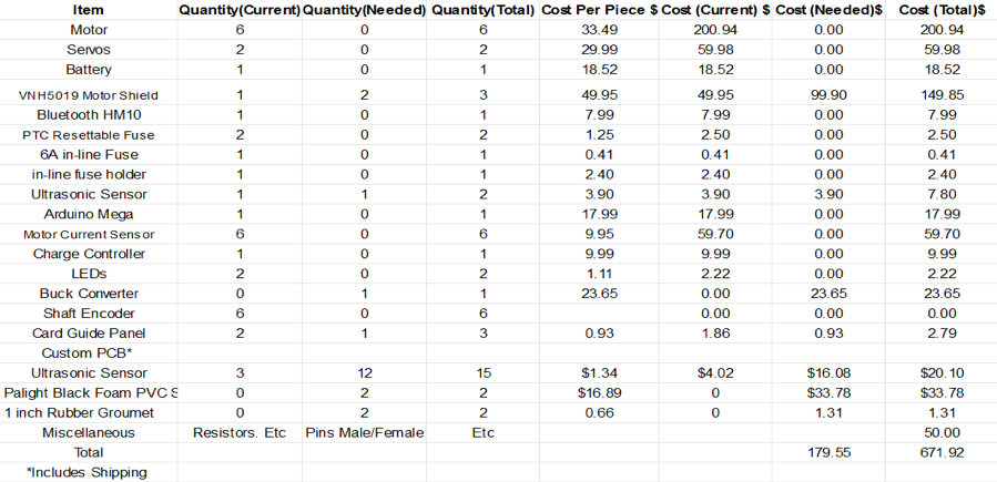
Figure 12: Cost Report
References/Resources
Content