Limbi Spring 2019
Limbi Servo Angle Accuracy (Rotational Tolerance) Test Plan
Author: Julie Liner (Missions, Systems, and Test)
Table of Contents
Introduction
This blog post overviews a test plan that was done to help improve the quality of our requirements by specifying a tolerance for the slot that the cross would be inserted into to dock. For this test a servo was controlled to go to a specific angle and the actual angle was measured. Based on the maximum error of this we were able to write requirement L2.1.6.1 based on the maximum displacement that could be possible. The name of the product being tested was the HS-422 Deluxe Standard Servo.
Steps to Perform Test
- From 90° set the servo to move to the left 30° then to the right 30°
- Measure and record the actual amount of degrees that the servo moves
- Repeat Steps 1 and 2 for 20° and 10° (this is to make sure the servo moves the same amount to the right and left)
- From center set the servo to move 5°
- Measure and record the actual amount of degrees that the servo moves
- Repeat Steps 4 and 5 for ,4° ,3° ,2° ,1° ,.5° (no movement should be expected for the last value)
Objective and Test Criteria
Reason and Outcome
The purpose of this test is to be able to determine the size of the hole for the cross so requirements can be updated. Once the test was completed we were able to determine the servo accuracy for the docks and the x-y error of the vernier servos.
Required Tools
Tools: Power source for servo, software/Arxterra app to control the angle that the servo is told to move, protractor to measure the actual angle that the servo has moved.
Test Environment: ECS 315
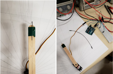
Pictures of Test Layout
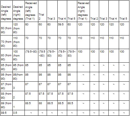
Measurements
Notes:
- Small jittery movement occurred at the .5 degrees, but it never settled on a number.
- The test was redone twice and the first time the data was discarded because of the code.
- The max servo error was 1 degree and occurred when 1 degree of movement was attempted.
- Human error must be accounted for due to the protractor and our inability to determine decimal movement.
- If the error was between .1 and .5 we rounded to .5, if it was above .5 it was rounded to 1 degree.
Post Test Analysis
Necessary changes to the end product: The specification for L2.1.6.1 was updated based on this.
Data reliability: The data is as reliable as we could get it with our resources but has approximately .5 degrees error (rounded up only) due to human error. To account for human error we ran the test through 5 trials. We also used an extended drawing of the angles to be able to more clearly see the angle variance than on a protractor (these angle drawings were checked with the protractor they were created with). The arm was used to see more variance in degrees, and the paper clip was used so we could visually align our site and the angle lines. Even with these measures taken we still had to round in increments of .5 degrees because the amount of error was too small to detect visually.
Results: Using the law of cosines the maximum displacement error was calculated based off of the maximum error of 1°:
|
Calculation of x-y location error: (±mm) |
||
| Joint servo A (inner joint) | Arm Length:177 | Error:3.09 |
| Joint servo B (Vernier control joint) | Arm Length:87 | Error:1.52 |
Table 2: Displacement Calculations
Corrective Actions: The error of the inner joint can be compensated for by the vernier servo since it is a very small amount compared to the length of the arm. The hole of the cross will be at least 1.52 mm larger than the cross based on these calculations. (Note: we are not using the inner joint for the error because it can be corrected by moving the vernier joint). If predefined movement is used then we will have to add account for the inner joint error.
Conclusion
Rapid prototyping and experimentation allowed us to improve our requirements. Originally we did not consider the size that the hole would need to be. After this experiment we were able to conclude that the hole for our docking slot would need to be at least 1.52mm larger than the cross itself due to the lack of precision in the movement of the servos and the error caused by the length of the arm.


