Pathfinder Chassis Generation 7
6-Wheel Electronic Differential
Author: Patrik Hertle (Electronics and Control)
Approval: Alexandrea Jackson (Project Manager)
The 6-wheel differential was implemented in the software as follows. Three different cases are distinguished using the Arxterra move command.
Case 1 – Drive straight ahead:
When driving straight ahead, there is no distinction is made between driving forwards or backwards, but only the data bytes (speed and direction) receiving from the control panel is transferred. Logically, these data bytes do not differ between left and right (has the same amount of speed and direction), so the case is also recognized.
Case 2 – Rotation:
The calculation for this was already done in this blogpost. The axis which the Pathfinder is to be rotated is placed in the middle of the Pathfinder (intersection of the diagonals). From the calculations, the motors on the left side should rotate in the opposite direction to the motors on the right side. However, since the direction is already specified in the command data bytes, this case can be recognized. On the other hand, only the speed of the middle wheels must be multiplied by 0. 545 (as calculated in the previously mentioned blog post), which makes a rotation at the position possible.
Case 3 – Driving curves:
The third and last case is driving curves. This case is a little more complex. First of all, we should understand the command which the Control Panel sends to our MCU in this case. If you first drive forward in case 1, both sides are moving in the same direction. However, if the vehicle is not stopped before driving left or right, the Control Panel maintains the average speed of the total speed but builds up a speed difference in the direction of travel. In other words, the speed is increased on one side and decreased on the other during driving. This happens until either the maximum speed or minimum speed has been reached (here the minimum speed is not negative, it is a standstill).
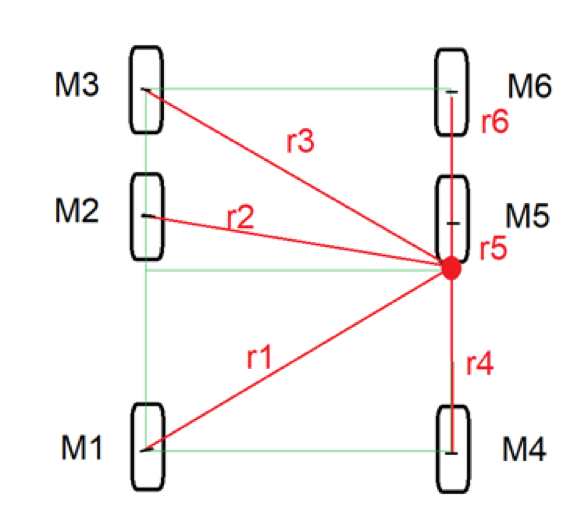
Figure : Illustration of the Radii between motor and axis for turning right
Driving curves differs from turning in a standing position as follows. The rotation axis is not in the center of the Pathfinder, but it was placed at the border for the calculation (this is where the rotation axis is in the limit case: left max. speed, right standstill). From the control panel we get the speed of the left as well as the right side. The following calculation is the same regardless if we are turning left or right. For the following calculations, we will assume we are making a right turn.
Thus applies:
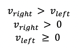
First, the respective radius is calculated for the axis of rotation. Since a circle has the largest circumference when the radius is the largest, the wheel furthest from the rotation axis must travel the longest distance. This means that the wheels M1 and M3 receive the maximum speed in the limit value (maximum speed at full turn).
![]()
From there the maximum speed for M2 can be calculated. However, since the slope of the curve depends on the speed difference controlled, the formula is designed as follows:
![]()
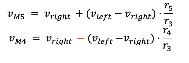
Thus an amount is subtracted from the controlled speed of the left side in dependence of the speed difference of the two sides, multiplied by a constant, which results from the reduced distance to the rotation axis. The right side is similar:
![]()
As already mentioned, the inclination depends on the speed difference. Since the wheels move perpendicular to the axis, the wheels in front must move faster and behind slower (Notice: since the axis can reach the speed value 0, the direction of rotation of the wheel below the axis changes in the maximum state).
The formulas for the remaining wheels can now also be derived from this.