Spring 2016 3D SMD: Preliminary Design Review
By: Bao Loc Doan (Project Manager)
Christine Vu (Systems Engineer)
Henry Nguyen (Electronics Engineer)
Nasser Alsharafi (Manufacturing)
Table of Contents
Program Objectives/Mission Profile
by Bao Loc Doan (Project Manager)
Program Objective Statement
When humans manually pick up and place down surface mount components onto a printed circuit board (PCB), there are problems with human accuracy and time efficiency. A pick and place surface mount device (SMD) is an automated device that can populate a PCB with surface mount components (resistors, capacitors, and IC chips) by referencing an EAGLE PCB file through the use of software. The pick and place SMD machine will be able to pick up the surface mount technology (SMT) components from 8 mm reel feeders and an integrated circuit (IC) tray and place the components down at the correct location until the board is finished. The customer has expressed the desire to create a pick and place SMD machine that can populate surface mount components as small as 0402 on all EE400D boards of Spring 2016 with the same specifications as the Madell Corporation Model DP2006-2. The customer has expressed the desire to keep the budget of the project below $650 and finished before the end of Spring 2016.
Mission Profile
Once an EAGLE PCB file provided by any project from EE400D up until Spring 2016 is uploaded, the pick and place SMD machine shall begin populating SMT components from four 8 mm reel feeders and one IC tray onto the PCB. The smallest SMT component that will be placed is component size 0402. The pick and place SMD machine will be modified from a Makeblock XY plotter and replicate the error specification of the Madell Corporation Model DP2006-2.
Requirements
Level 1 Program/Project Requirements
by Bao Loc Doan (Project Manager)
To satisfy our customer, a list of requirements that our end product needs to meet were created. These requirements will move the design forward and provide traceability to our program objectives and mission profile.
- The SMD pick and place machine shall pick up and place down all SMT components provided by any EE400D PCB up until the end of Spring 2016.
- The SMD pick and place machine shall be modified from an XY Plotter to have the same error specification of Madell Corporation Model DP2006-2 (n.d).
- Software for the SMD pick and place machine shall accept all EAGLE PCB files of EE400D projects up until Spring 2016.
- The SMD pick and place machine shall have four 8mm reel feeders and one IC tray.
- SMT component size 0402 shall be the smallest component that the pick and place SMD machine can pick up.
- Total cost of finished project must be under $650.
- Deadline to complete the pick and place SMD machine shall be before the end of Spring 2016.
Level 2 System/Subsystem Requirements
by Christine Vu (Systems Engineer)
Level 2 System and Level 2 Subsystem Requirements are listed below. The process of forming requirements is not only crucial to the overall design of the project but also difficult to form due to the customer’s needs and the nonlinearity of designing. Through many revisions, the level 2 requirements were officially determined. Because this project is new to the Arxterra blog, references were obtained through scholarly journal research and outside resources other than the Arxterra blog.
Source Material:
Arra, M. , Geiger, D. , Shangguan, D. , & Sjöberg, J. (2004). A study of smt assembly processes
for fine pitch csp packages. Soldering & Surface Mount Technology, 16(3), 16-21.
CadSoft Computer GmbH and CadSoft Inc. (2011). EAGLE Freeware. Retrieved from:
http://www.cadsoftusa.com/download-eagle/freeware/
Changzhou Douwei Electric Co. Ltd. (n.d.). 42BYG Stepping Motor. Datasheet.
Makeblock. (2014, June 9). XY Plotter 2.0 How it works? Retrieved from:
https://www.youtube.com/watch?v=gY0xMYrWBDg
Panasonic. (2014, Feb. 4). Precision Thick Film Chip Resistors. Datasheet.
Shenzhen Maker Works Technology Co., Ltd. (2013). X-Y Plotter Robot Kit. Retrieved from:
http://www.makeblock.cc/xy-plotter-robot-kit/
TCI Precision. (2005). Blanchard Grinding. Retrieved from: http://tciprecision.com/machine-ready-blanks/capabilities/Blanchard%20Grinding
Telecommunications Industry Association. (2001). TIA/EIA-568-B.1: Commercial Building
Telecommunications Cabling Standard.
VBsProjects. (2014, July 12). Homemade SMD Pick and Place Machine – complete cycle.
Retrieved from: https://www.youtube.com/watch?v=CRSLbo_8nTQ#t=7m34s
Notes on Requirements:
L2 – # – Level 2 System Requirements (i.e. L2 – 1)
L2 – #x – Level 2 Subsystem Requirements (i.e. L2 – 1a)
| L1 – 1 | The SMD pick and place machine shall pick up and place down all SMT components provided by any EE400D PCB up until the end of Spring 2016. |
| L2 – 2: Working area must be within 12.2”x15.35”(310mmx390mm) based on the Makeblock X-Y Plotter Robot Kit. | |
| L2-1a | Surface to hold PCB shall be smooth with dimensions tolerances to be ±.001″, parallelism to .001″, and flatness to .001″ (TCI Precision, 2005). |
| L2-1b | PCBs laid out for assembly shall be on a surface at 0° with respect to the floor. |
| L2-1c | All wires using RJ25 connectors shall have a minimum bend radius of 4x its diameter (Telecommunications Industry Association, 2001). |
| L2 – 3: Pick and place SMD machine shall self-correct all orientation of IC chips before placement. | |
| L1 – 2 | The SMD pick and place machine shall be modified from an XY Plotter to have the same error specification of Madell Corporation Model DP2006-2 (n.d). |
| L2 – 4: Makeblock XY Plotter motors shall be modified to a maximum of 0.05 mm error. | |
| L2-4a | Resolution of all axes motors shall be less than 1.8°/step. |
| L2-4b | Z-axis motor shall move the vacuum system at 90° with respect to the floor. |
| L1 – 3: Software for the SMD pick and place machine shall accept all EAGLE PCB files of EE400D projects up until Spring 2016. | |
| L2 – 5: Software shall translate all EagleCAD files from EE400D PCB’s to G-Code files. | |
| L2-5a | Software shall include all x-y-z coordinates for SMD pick and place machine to read. |
| L1 – 4: The SMD pick and place machine shall have four 8mm reel feeders and one IC tray. | |
| L2 – 6: All SMT resistors and capacitors shall remain in cut-tape of the reel feeders until the vacuum nozzle is ready to pick up the component. | |
| L2-6a | All reel feeders shall be installed on the working area, 12.2”x15.35”(310mmx390mm). |
| L2-6b | Bracket to hold cut-tape of the reel feeders shall be higher than 1.10 mm. |
| L2-6c | All motors used to peel off cut-tape of reel feeders must rotate 360°. |
| L2 – 7: IC tray shall store all IC chips required for one PCB assembly. | |
| L2-7a | IC tray shall be installed within working area, 12.2”x15.35” (310mmx390mm). |
| L1 – 5: SMT component size 0402 shall be the smallest component that the pick and place SMD
machine can pick up. |
|
| L2 – 8: Vacuum system shall be able to pick up all SMT components as small as size 0402. | |
| L2-8a | Vacuum nozzle shall be smaller than 0.50 ± 0.05 mm. |
| L2-8b | A solenoid valve for vacuum system shall keep a stable temperature under 160° F during operation. |
| L1 – 6: Total cost of finished project must be under $650. | |
| L2 – 9: All receipts and invoices shall be recorded and stored to verify all purchases. | |
| L1 – 7: Deadline to complete the pick and place SMD machine shall be before the end of Spring 2016. | |
Design Innovation
System/Subsystem Design
Product Breakdown Structure
By Christine Vu (Systems Engineer) and Henry Nguyen (Electronics Engineer)
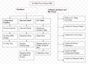
Figure 1. Product Breakdown Structure
The Product Breakdown Structure (PBS) shows all the functional blocks of our pick and place 3D SMD machine. The hardware is split into three different categories: Component Feeders, Vacuum Head, and X-Y Table. We will need a minimum of 4x micro servos to control our 4x 8mm reel feeders and an IC chip tray. The Vacuum head will consist of a vacuum to suction the components, a syringe or vacuum pen to pick up our components, a solenoid valve to block airflow and allow our components to be placed, and finally a stepper motor for rotation of the A axis. The X-Y Table is purchased from MakeBlock; however, we will need an aluminum surface table, slider rods, stepper motors, and calibration sensors to orientate our components. For software, we plan on using Arduino to program the Arduino Uno and Me Orion microcontrollers. Software must be able to convert Gerber files into G-code which can be read by our Me Orion microcontroller. We will need to be able to control all axis of our machine, the calibration sensor, component feeders, and solenoid valve through software.
Software Design
by Christine Vu (Systems Engineer)
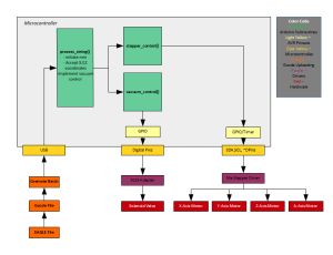
The Makeblock X-Y Plotter Robot Kit software begins with the submission of a gcode file. An EAGLE file is submitted and converted to gcode for the Arduino sketch to translate. There are three main subroutines to process the gcode coordinates–process_string, stepper_control, and vacuum_control. In process_string, the code searches for x-coordinates, y-coordinates, and z-coordinates. In the stepper_control, x-,y-, and z-coordinates, are processed to move the motors. The vacuum_control is used to detect when the vacuum tubing should open and close according to the change in the z-coordinates.
Figure 2. Software Design
Electronic System Design
Source Material
Me Orion:
- Schematic:
- Makeblock. (2014, June 25). Makeblock_Orion_Schematic_V1.0.PDF. Retreived Februrary 18, 2016, from http://learn.makeblock.cc/learn/resources/Makeblock_Orion_Schematic_V1.0.PDF
- Specifications:
- Me Orion(Base on Arduino UNO). (n.d.). Retrieved February 26, 2016, from http://www.makeblock.cc/me-orion-base-on-arduino-uno/
Me Stepper Driver:
- Schematic:
- Makeblock. (2014, June 25). Me_Stepper_Motor_Schematic.png. Retreived Februrary 18, 2016, from
- http://wiki.makeblock.cc/images/4/40/Me_Stepper_Motor_Schematic.png
- Specifications:
- Me Stepper Motor Driver. (n.d.). Retrieved February 26, 2016, from http://www.makeblock.cc/me-stepper-motor-driver/
System Block Diagram
By Christine Vu (Systems Engineer) and Henry Nguyen (Electronics Engineer)
Figure 3. System Block Diagram
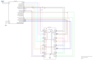
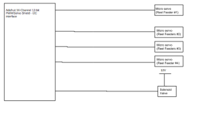
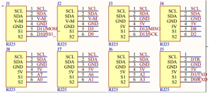
The images above is the system block diagram for our pick and place 3D SMD Machine. We are currently using a Me Orion microcontroller provided by Makeblock. This microcontroller has an Atmega3280-AU microprocessor, 8 Me RJ25 ports, two Me Stepper drivers, and 3 Me RJ25 adaptors. The pin outs for each Me RJ25 port is shown above which is connected to our microprocessor. Every port on our Me RJ25 has a SDA and SCL which is our I2C. This will be all connected to our PC4 and PC5 respectively. We will be using ports J1, J2, J3, J6 and J7. The first two ports is to control our X and Y axis stepper motors. J6 and J3 is to control our X and Y axis limit switches respectively. Finally J7 is to control our Z-axis micro servo. We plan on having another micro servo to serve as our A-axis component orientation which may connect to any other available ports. Next we are considering a Adafruit 16-Channel I2C interface in order to connect all of our micro servos for our reel feeders. We currently will need 4 servos for this purpose; however, for future semesters, they may need to implement more reel feeders. Our vacuum will be constantly running on a separate power source. The solenoid valve will close off the vacuum to prevent suction. This will allow our components to be placed onto our PCB after our machine picks it up.
Interface Definition
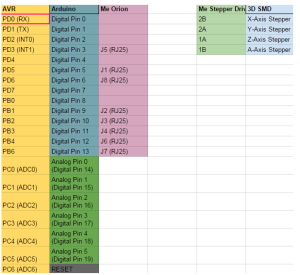
Figure 4. Interface Matrix
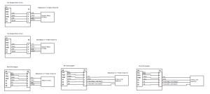
The image above is the interface matrix for our pick and place 3D SMD machine. We will be utilizing an Arduino Uno, Me Orion, and Me Stepper Driver. Me Orion and the Me Stepper Driver came with our X-Y Plotter. This Me Orion is based off of an Arduino Uno, which will allow us to code using Arduino, Scratch. and AduBlock. We will be using this microcontroller because it has 8 RJ25 ports which will be useful for all of our actuators. The Me Stepper Driver will be used to precisely control our stepper motors by operating our motors in full, half, quarter, eighth, and sixteenth step modes. This modes can be easily changed using the built-in DIP Switch. We will need 4 Me Stepper Drivers in order to control all of our stepper motors on each axis (x,y,z,A).
Figure 5. Me Orion Schematic
Figure 6. Me Stepper Driver Schematic
Specification for Me Orion:
Operating Voltage: 6-12V DC power;
Microcontroller: ATmega238;
Detecting Angle: prefer at 30 degree angle;
Dimension: 80 x 60 x 18 mm (Length x Width x Height);
Specification for Me Stepper Driver:
- Max current: ±1.35A
- Max motor drive voltage: 25V
- Note: Me BaseBoard max supply voltage 12V
- Logic voltage: 5V
- Dimensions: 48mm*24mm(Length × Width)
Mechanical Design
By Nasser Alsharafi (Manufacturing)
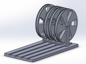
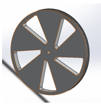
In this part of the project for the XY plotter I am coming up with the design of a Reel Feeder. The main purpose of a reel feeder is to feed the machine with the surface mounted parts. The reel feeder is made of aluminum. The main function of the Reel Feeder wheel is to roll and pass on the parts to the Reel Feeder base, which then the parts will be picked up by the vacuum.
Figure 7. Complete reel feeder assembly 3D model
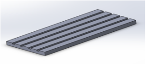
Figure 8. Reel feeder base
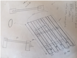
The base sheet of the reel feeder has four channels called the grooves in which the tape passes through. The base sheet of the reel feeder has a length of 270 mm and a width of 82 mm. Each of the grooves on the base sheet of the reel feeder has a width of 8 mm. The main function of the reel feeder is to guide the tape to the part of the feeder where the chip is first pulled and then picked by a vacuum pen. This action helps in preparation of the next chip. After, the chip is taken by the vacuum pen and is placed on the PBC board.
Figure 9. Reel feeder wheel
Figure 10. Drawing of initial reel feeder base
Currently, our reel feeder is manual, so there can be further improvements by making the reel feeder automatic. In order to make the reel feeder automatic, I have to design a mounting bracket for 4 micro-servos. Each channel has single micro-servo to pull back the tape while pushing the reel forward. This will be implemented by working with Henry Nguyen to control the micro-servos.
Design and Unique Tasks
Design
by Nasser Alsharafi (Manufacturing)
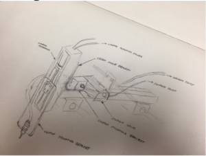
The pick and place vacuum nozzle system was sketched out. We had to take into consideration the weight of the entire system and make sure our actuator can support that weight.
Figure 11. Actuator Design
Unique Tasks
By Bao Loc Doan (Project Manager), Henry Nguyen (Electronics Engineer), Christine Vu (Systems Engineer)
The stepper motor movement for the X and Y axis were mirrored. If we wanted the XY plotter to move left, it would move right. If we wanted the XY plotter to move up, it would move down. The solution was to change the connection of the wires to the opposite orientation. There are 4 wires that are output from the stepper motor. The wire colors are green, blue, red, and black. Rather than inputting it as green,blue,red,black into the connector, we switched the orientation to black, red, blue, and green. This changed the stepper motor orientation.
The limit switches also were not working correctly. When the XY plotter was supposed to stop due to it reaching the limits of its working area, the XY plotter kept going and ramming into the edges of the XY plotter. The manual for the XY plotter had the limit switches going from an RJ25 into port 5 of the Arduino. This was wrong. After hours of debugging and testing software, we realized this error. The limit switches ended up working after plugging it into port 7 of the Arduino.
Project Status
by Bao Loc Doan (Project Manager), Christine Vu (Systems Engineer), and Henry Nguyen (Electronics Engineer)
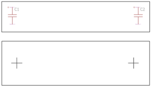
Currently, we were able to successfully translate an EAGLE PCB file to G-CODE. There are two layers, TORIGINS and TPLACE, specifically from EAGLE PCB that were used. TORIGINS displays the centerpoint of each component and TPLACE displays the outline of the component so the system could possibly recognize which orientation the component should be placed. The issue that we are currently facing is interpreting all the G-CODE location sets and translating it in a way for our XY plotter to properly read them.
Figure 12. Torigins and Tplace layers
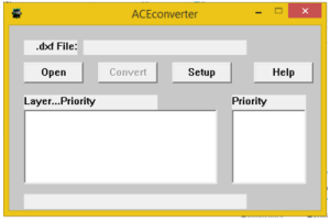
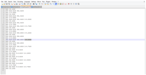
In order to successfully translate EAGLE to GCODE, the EAGLE file needs to be exported into a .DXF file. Then we can use ACEconverter to translate the .DXF file to GCODE. Using Notepad++, then the Z-axis can be modified to our needs.
Figure 13. ACEconverter and Notepad++
A trade-off study on the vacuum system was conducted as well. We are currently deciding which aquarium pump to use, whether it is 20 gal, 40 gal, or 100 gal. There are still experiments that need to be conducted and we will provide updates when those experiments are done. The trade-off study blog was created and can be seen here.
A separate blog has already been made for the XY plotter that was purchased and that blog will explain all design ideas as well as provide updates on how the XY plotter functions. The blog can be seen here.
Work Breakdown Structure
By Bao Loc Doan (Project Manager) and Christine Vu (Systems Engineer)
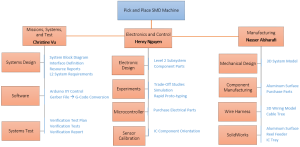
Our Work Breakdown Structure (WBS) was modeled after the Robot Project WBS. Each division will have tasks delegated to them and will be their primary responsibility to complete. As mentioned in 05 Preliminary Project Plan PDF, the WBS will be a “… hierarchical tree structure where each node (group) is the responsibility of only one engineer.” A completion of the WBS will indicate a successful project. The chart below will be the pick and place SMD machine WBS.
Figure 14. Work Breakdown Structure
Source Material
[1] G.Hill (2016, Feb). 05 Preliminary Project Plan [Online]. Available: 05 Preliminary Project Plan PDF
Project Schedule
A project schedule will lay out the deadlines that each engineer needs to conform to when assigned to their tasks. The schedule will allow the engineer to understand how much time they have left as well as the progression needed to complete the project. When deadlines are not met, there will be a chart illustrating the remaining cumulative work as well as baseline cumulative work.
Top Level Schedule
By Bao Loc Doan (Project Manager) and Christine Vu (Systems Engineer)
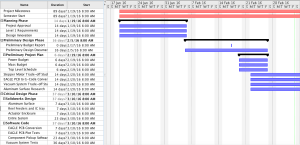
The top level schedule tasks were derived from our WBS. Each module in the WBS were taken into account. While working with the systems engineer, we developed a schedule that will divide all tasks in a progression that we believe will lead to project completion. Each required task will have a time estimate, and failure to meet the time estimated will result in the delay of every task assigned after. The chart below is the pick and place SMD top level schedule.
Figure 15. Top Level Schedule
System/Subsystem Level Tasks
By Henry Nguyen (Electronics Engineer), Christine Vu (Systems Engineer), and Nasser Alsharafi (Manufacturing)
Reference top level schedule for system/subsystem level tasks.
Burn Down and Project Percent Completion
by Bao Loc Doan (Project Manager)
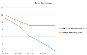
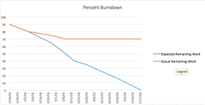
A burn down graph is a visual representation of the expected progression and remaining progression. The top level schedule was created in ProjectLibre, so we had to use Excel to create a burn down graph. The task burn down and the percent burn down will be shown below.
Figure 16. Burn Down Graphs
System Resource Reports
Mass Report
By Christine Vu (Systems Engineer)
| Vacuum System Components | Preliminary Mass (g) | Uncertainty (%) | Margin (±g) | Expected Mass (g) | Actual Mass (g) |
| Stepper Motor (A-Axis) | 290.00 | 5% | 14.5 | 304.50 | |
| Stepper Motor (Z-Axis) | 290.00 | 5% | 14.5 | 304.50 | |
| Solenoid Valve | 99.79 | 5% | 4.99 | 104.78 | |
| Makeblock Stepper Driver (2 ct.) | 40.00 | 5% | 2 | 42.00 | |
| Vacuum Syringe | 68.00 | 5% | 3.4 | 71.40 | |
| Vacuum Tubing (25-ft.) | 68.00 | 5% | 3.4 | 71.40 | |
| Project Allocation | Trade-Off Study will be obtained | ||||
| Total Expected Mass | 898.58 | ||||
| Total Margin | 42.7895 | ||||
| Total Actual Mass | |||||
| Contingency | |||||
Table 1. Mass Report
Summary
The pick and place SMD machine will not need a power resource report because we are not limited in power. A waiver request will be submitted for approval.
The mass resource report is on the vacuum system to determine the mass. The stepper motor expected weight have been obtained from the Makeblock specifications on their X-Y Plotter Robot Kit (Shenzhen Maker Works Technology Co., Ltd., 2013).
The Makeblock Stepper Motor Driver is a component used to control the stepper motor with the ArduinoUno. It contains a stepper driver chip, 4 wire bi-polar stepper motors, a potentiometer, DIP switch, and a heat sink.
Because the components have not been purchased, project allocation, actual mass, and contingency will be obtained after trade-off studies have been conducted.
Source Material:
Shenzhen Maker Works Technology Co., Ltd. (2013). Me Stepper Motor Driver. Retrieved from:http://www.makeblock.cc/me-stepper-motor-driver/
Project Cost Estimate
By Bao Loc Doan (Project Manager) and Christine Vu (Systems Engineer)
| Resource | Unit Price ($) | Quantity | Shipping Cost ($) | Preliminary Cost ($) | Uncertainty (%) | Margin (±$) | Expected Cost ($) | Actual Cost ($) |
| MakeBlock XY Plotter Robot Kit | $267.66 | 1 | $0.00 | $267.66 | 8.00% | $21.41 | $289.07 | $267.66 |
| Tetra Aquarium Pump | $17.59 | 1 | $0.00 | $17.59 | 8.00% | $1.41 | $19.00 | |
| 8 mm Reel Feeders (Holds 4) | $32.00 | 1 | $0.00 | $32.00 | 8.00% | $2.56 | $34.56 | |
| Micro Servo | $7.00 | 4 | $0.00 | $28.00 | 8.00% | $2.24 | $30.24 | |
| 12V Solenoid Valve | $10.00 | 1 | $0.00 | $10.00 | 8.00% | $0.80 | $10.80 | |
| Aluminum Surface & Machinist Labor | $60.00 | 1 | $0.00 | $60.00 | 8.00% | $4.80 | $64.80 | |
| 42BYG Geared Stepper Motor | $60.00 | 2 | $0.00 | $120.00 | 8.00% | $9.60 | $129.60 | |
| Vacuum Tubing (25-ft) | $5.00 | 1 | $0.00 | $5.00 | 8.00% | $0.40 | $5.40 | |
| MakeBlock Stepper Driver | $18.00 | 1 | $0.00 | $18.00 | 8.00% | $1.44 | $19.44 | |
| Sensor Calibration | $50.00 | 1 | $0.00 | $50.00 | 8.00% | $4.00 | $54.00 | |
| Connectors | $2.00 | 2 | $0.00 | $4.00 | 8.00% | $0.32 | $4.32 | |
| $0.00 | $0.00 | 8.00% | $0.00 | $0.00 | ||||
| Project Allocation | $650.00 | |||||||
| Total Expected Cost | $612.25 | |||||||
| Total Margin | $48.98 | |||||||
| Total Actual Cost | $267.66 | |||||||
| Contingency | $86.73 | |||||||
Table 2. Cost Report
Summary
The cost report supports all parts needed so far to construct the pick and place SMD machine for Spring 2016.
The Makeblock XY Plotter is an XY plotter that can be easily modified to our needs. This specific XY plotter has a working area of 12” x 15” so it can easily fit our PCB fabrication requirements (4” x 3.2” as per free Eagle CAD board working area) and additional reel feeders. The Makeblock XY plotter ships all the parts as a kit and would be much more efficient to build since we would no longer need to design the entire XY plotter. The accuracy of this XY plotter needs to be increased by a factor of 2 (as requested by the customer) and a simple solution is to implement a geared stepper motor.
The Makeblock Gearbox Stepper Motor will be implemented into our pick and place SMD machine so our precision error meets customer standards of 0.002”.
The aquarium pump, solenoid valve, tubing, syringe, and connectors shall be used for the vacuum system in the pick and place SMD machine. The aquarium pump is easily modified to become a vacuum and the solenoid valve with brass fittings will control when the vacuum suctions in order to pick and up and place down the components as intended. The tubing, syringe, and connectors will connect each individual component to make the vacuum system.
All of our surface mount resistors and capacitors shall be placed in the 4x 8 mm reel feeders so they can be populated onto the PCB. After Spring 2016, 16x 8 mm reel feeders will be implemented into the pick and place SMD machine.
The aluminum surface will be the working area of the entire pick and place SMD machine. The machinist labor is included into the price. The Makeblock XY plotter will need to securely fit into the aluminum surface and there will also be an aluminum clamping system that needs to be drilled into the aluminum surface.
The Makeblock stepper motor driver will be used in conjunction with the Makeblock stepper motor to control our vacuum nozzle. In order for the vacuum to be able to pick up components, the ability to move in the Z-axis is required. We have plans to implement one Makeblock stepper motor on the z-axis and will need the circuitry required.

