GradBot Generation 1
Author/s: Taylor Manning, D&M, Shannon Hormozian, PM, MST
Verification:
Approval:
Table of Contents
Executive Summary
What better way to commemorate your child’s graduation than by buying GradBot to escort them across the big stage and share this moment with them. GradBot is a prototype of the Astromech Droid, BB8, as seen in the latest Star Wars movies. In this first iteration, the unique toy internally sports the Walter Pyramid in honor of Cal State Long Beach’s iconic landmark. Geared for graduates aged 12 and older, this charming little robot will follow the graduate in a relatively straight path across the entire stage donned with school colored mortarboard. It will follow at the average walking speed of a graduate (approximately 1.4 m/s) and will be able to cross level, hard or thin carpeted stage flooring. It will require minimal assembly as the wheels, motors, circuit board, and associated wiring will be mounted within the lower half of the robot. Only action required is manually turning on the circuit board, connecting the Arxterra App in order to operate GradBot, and enclosing it in the sphere.
Program and Project Objectives
Program Objectives
The Robot Company (TRC) will be debuting its 2019 line-up of toy robots and associated games at the Toy-Invasion 2019 convention in Burbank CA on January 6, 2019. Your team’s assignment is to make the 3D printed and/or laser-cut prototypes to be showcased at the convention, prior to production starting in the second quarter of 2019. The robots will feature our new ArxRobot smart phone application and the Arxterra internet applications allowing children to interact and play games around the world. In addition, the robots should be able operate autonomously in game mode. See game(s) (i.e, mission objectives) assigned to your robot by the Game Division. To decrease electronics cost, interoperability between all TRC robots will be maintained by incorporation of the 3DoT board, developed by our Electronics R&D Section. Modification of downloadable content is limited to software switch setting and robot unique graphics of the smart phone and Arxterra applications. Modifications of electronics is limited to custom 3DoT shields as required by the unique project objectives of your robot. The Marketing Division has set our target demographic as children between the ages of 7 and 13, with a median (target) age of 11. To decrease production costs, please keep robots as small as possible, consistent with our other objectives. As with all our products, all safety, environmental, and other applicable standards shall be met. Remember, all children, including the disabled are our most important stakeholders. Our Manufacturing Division has also asked me to remind you that Manufacturability and Repairability best practices must be followed.
GradBot’s Project Objective
GradBot presents graduates age 12+ with the unique opportunity to enhance their graduation experience by having a robot companion accompany them across the stage as they get their diploma. With an innovative design that implements two DC motors operating inside a sphere to create its rolling motion, this robot can operate in any X-Y direction by simple inputs to its associated phone app. The spherical body allows this toy robot to cross most level, wood or thin carpeted stage flooring and can overcome minor obstacles as it tends to naturally navigate away from them once it has come in contact with the obstacle and the motors are still in operation. By building this robot around the intelligently crafted 3dot board, future designers will be able to re-create and improve the overall design of GradBot and create an optimal version for future graduates.”
More detailed information can be found in the Project Objective & Mission Profile blog post.
Mission Profile
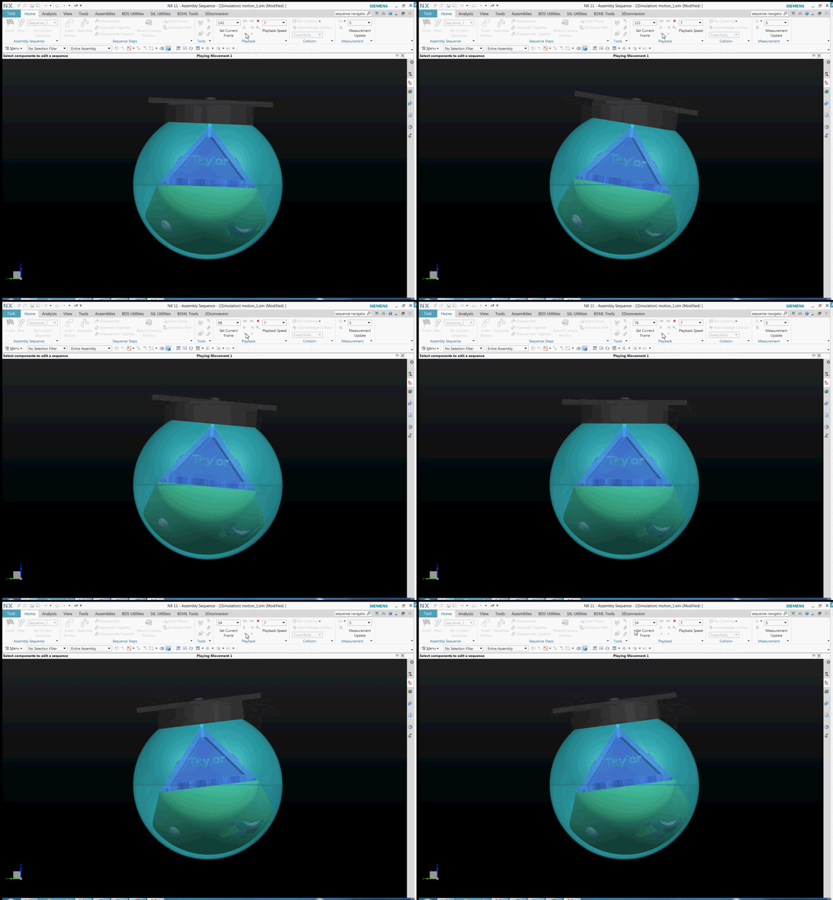
GradBot, a prototype toy for graduates aged 12+, will be demonstrated by having a graduate turn on the 3dot board, assemble all internal pieces, enclose the assembly within the sphere, place the mortarboard on top of the sphere and connect to the Arxterra App. From there, the graduate will place the robot at the beginning of the stage and be able to control GradBot to follow him across the entire length of the stage using the app’s controls. Once the crossing of the stage has been accomplished, GradBot has completed its intended mission and shall be removed from the stage by the graduate.”
More detailed information can be found in Project Objective & Mission Profile.
Project Features
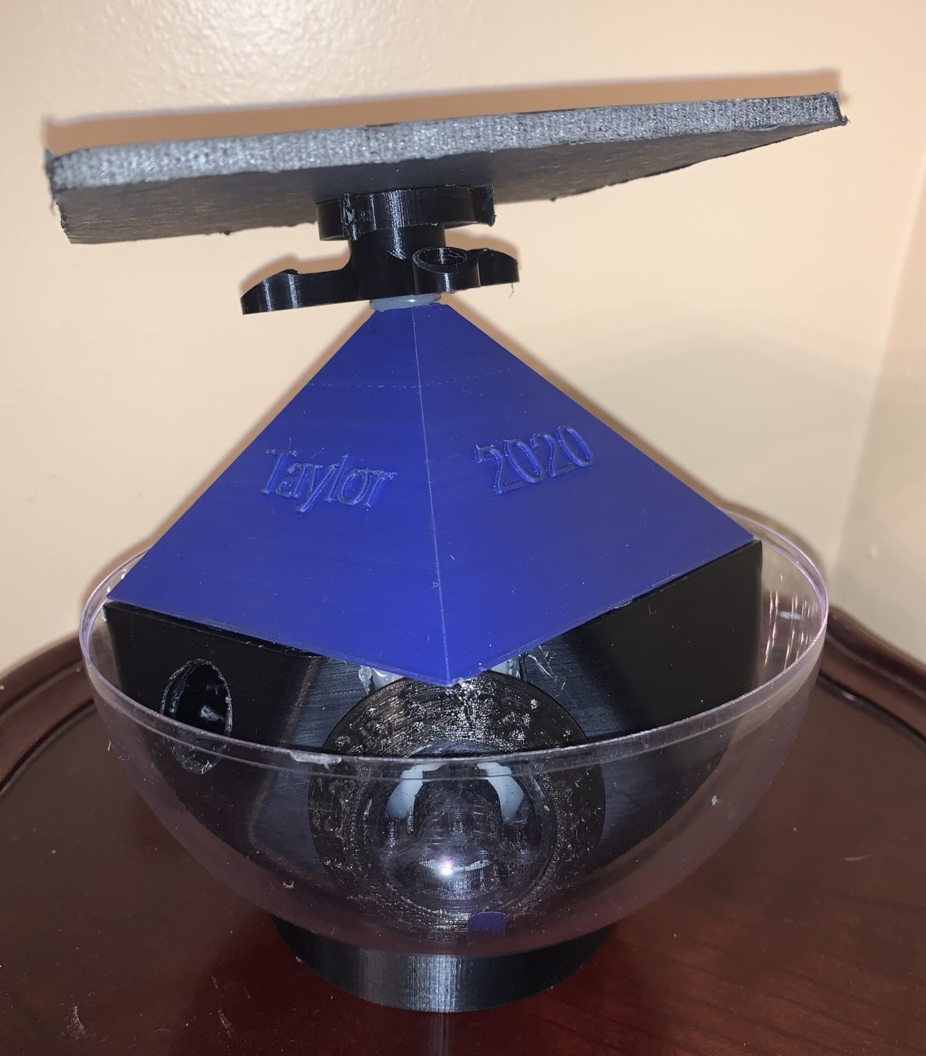
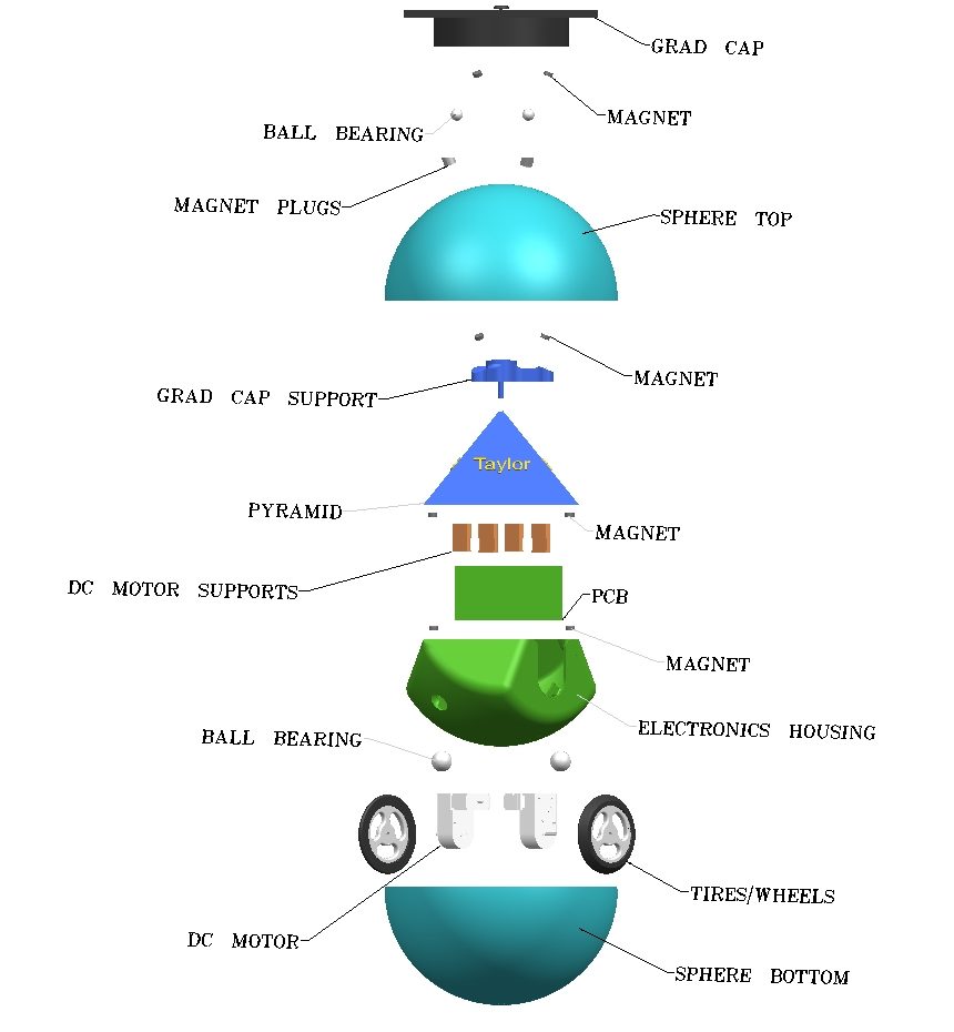
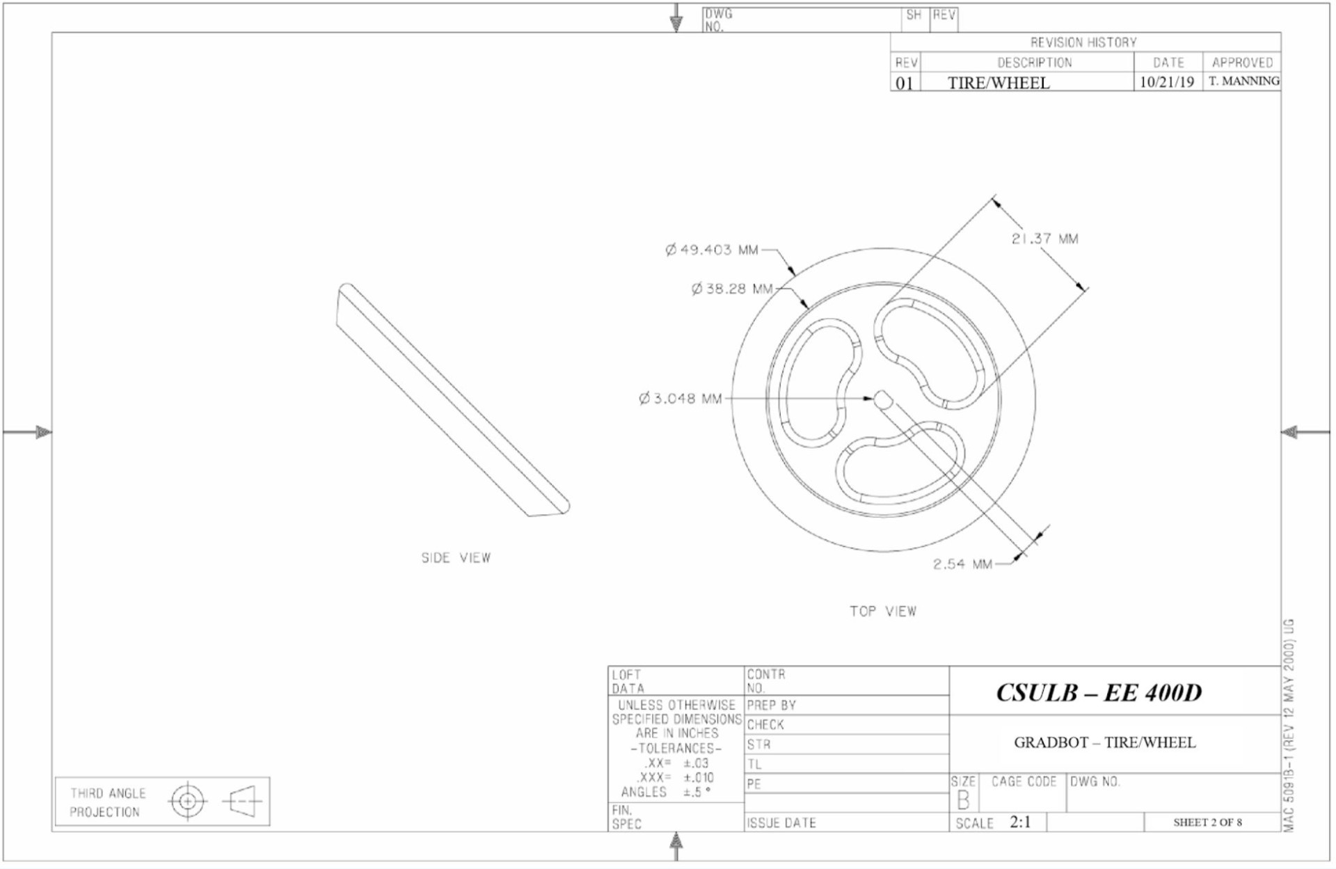
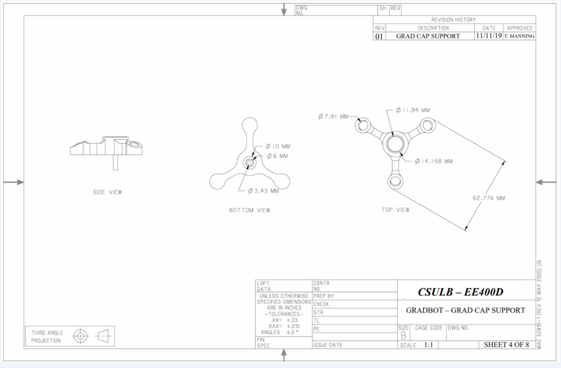
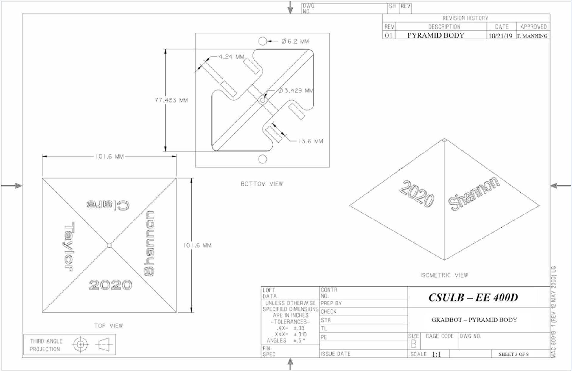
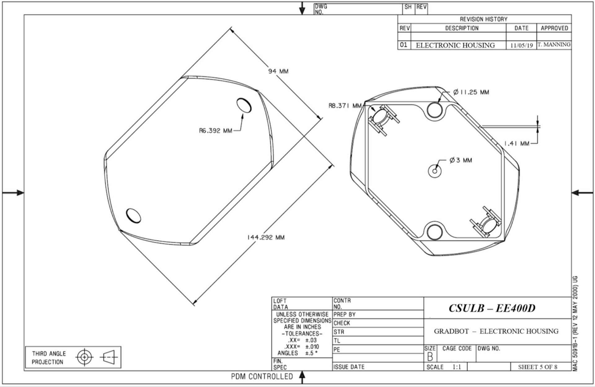
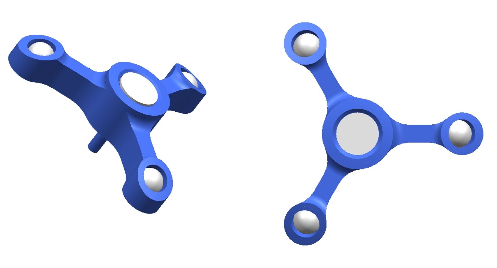
GradBot is a new project with innovative designs that led to more efficient operation for a robot of this type. Starting at the top, we have the mortarboard that features a 3-armed spindle whose arms are located approximately 120 degrees apart with bearings in each arm to provide an almost frictionless motion along the top of the sphere during operation. A magnet lies within the center of it and will correspond to the internal 3-armed mechanism that sits atop the pyramid to magnetically secure the mortarboard at the apex of the sphere. The sphere used in this assembly is a store bought, giant ornament that encapsulates the inner assembly via the inner and outer lip of each half of the sphere. The pyramid is a simple design using the basic shape with a slope of 51 degrees. The center and bottom were cored out to improve access and weight distribution. The DC motor supports fasten the motors to the bottom of the pyramid or motors can be affixed to the slots cut out for them in the electronics housing for easier assembly. The electronics housing is one of the more intricate designs on the robot as we had to match the base of the pyramid’s perimeter and gradually taper into a spherical shape to match the contour of the outer sphere. Bearings were inlaid in the electronic housing for added stability during operation. The other intricate design came in with the tires and wheels. Using the contour of the sphere again as a guide, angled tires with nodules and a hollow center were designed and implemented to ensure optimal surface contact and significant traction for more efficient operation.
More detailed information can be found in the final blog post for the Mechanical Design & Manufacturing.
Requirements
To best meet the customer’s expectations, GradBot’s development made sure to remain within the constraints imposed by the customer, Engineering Standards, and EH&S Standards. To best accomplish this, the following industry standards and constraints as well as generated requirements were followed for successful delivery of product to the customer. The following are GradBot’s Constraints as well as Level 1 and Level 2 functional and performance requirements as derived from the project’s objective.
More detailed information about the requirements can be found in the final blog post for the CDR.
Engineering Standards and Constraints
Constraints
- GradBot’s internal rover must be less than 6 inches on its maximum side.
- Gradbot must move at a minimum of 1.4 m/s (average walking speed).
- Gradbot must not exceed 3 kg.
- Disassembly and reassembly of the robot shall be constrained to 20 min total
Standards
- Software shall be written in the Arduino De facto Standard scripting language and/or using the GCC C++ programming language, which is implements the ISO C++ standard (ISO/IEC 14882:1998).
- All 3DoT robots shall incorporate the 3DoT v8 or later series of boards.
- All 3DoT robots shall be controlled via Bluetooth 4.0 in compliance with the Bluetooth Special Interest Group (SIG) Standard (supersedes IEEE 802.15.1).
Program Level 1 Requirements
1.1 The robot shall be controlled in any x-y direction
- Verification by testing
1.2 The robot shall be aesthetically pleasing
1.3 The pyramid will be in a sphere
1.4 The robot shall have a graduation cap
1.5 The robot will be designed as a prototype for a toy (ages 12+)
Project Level 1 Functional Requirements
The most unique of our functional requirements would have to be the overall idea that our robot will not be moving by having it’s wheels directly touching the ground, but instead our pyramid shaped bot in encapsulated in a clear acrylic sphere and the wheels grip and roll the ball and bot forward at once.
System/Subsystem/Specifications Level 2 Requirements
2.1-1 The robot shall be controlled and operated using a bluetooth module connected to the Arxterra app and connect within less than a minute when other v9 boards are not present.
- Verification by testing with the v9
2.1-2 The robot will have two gm6 motors with encoders that connect to an IMU.
- Verification by comparison of different motors (See Trade-Off)
- Verification by breadboarding to collect coordinate data
2.1-3 The robot will have two wheels that drive the motor at 1.5 m/sec
- Verification by testing the robot when fully assembled
2.1-4 The robot should have a follower mode
2.1-5 The robot should move in a straight path with accuracy of ±6 inches
- Verification by testing along a drawn straight path to see amount of deviation
2.1-6 The robot should have a low center of mass for added balance
- Verification by trial and error, adding/subtracting weight until best results with lowest COM is found
2.2-1 The wheels, internal electronics, and all sensors will be hidden
2.2-2 The pyramid will be shaped like a 3D printed replica of the Walter Pyramid at CSULB
2.2-3 The pyramid body will be blue like the Walter Pyramid at CSULB
2.3-1 The sphere will be clear
2.4-1 The grad cap shall be held on with magnets and 3D printed mechanisms
- Verification by testing mechanisms on static sphere.
2.4-2 The grad cap shall remain at the top of the clear sphere when robot is at 90°±10°
- Verification by testing on robot in motion.
2.5-1 The robot should stay intact during normal operation
Allocated Requirements / System Resource Reports
Project Report
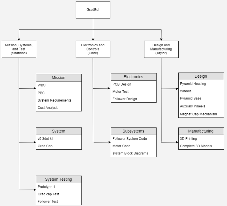
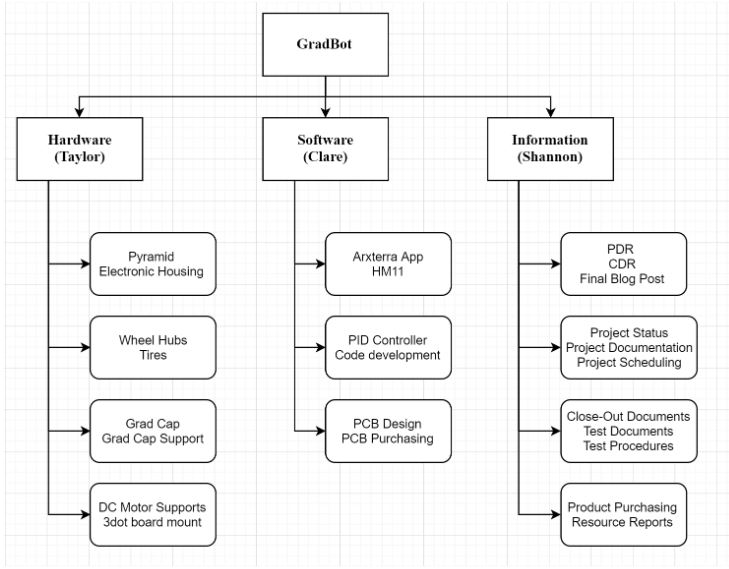
Project WBS and PBS
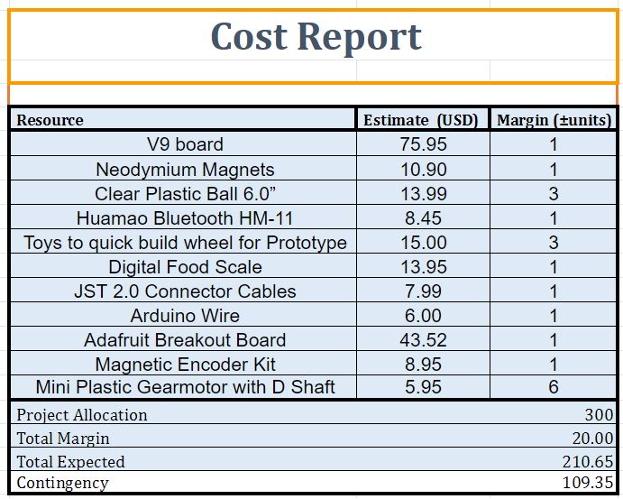
Cost
The cost report kept us on track to stay under our project allocation of $300. A more detailed list with links included can be found here.
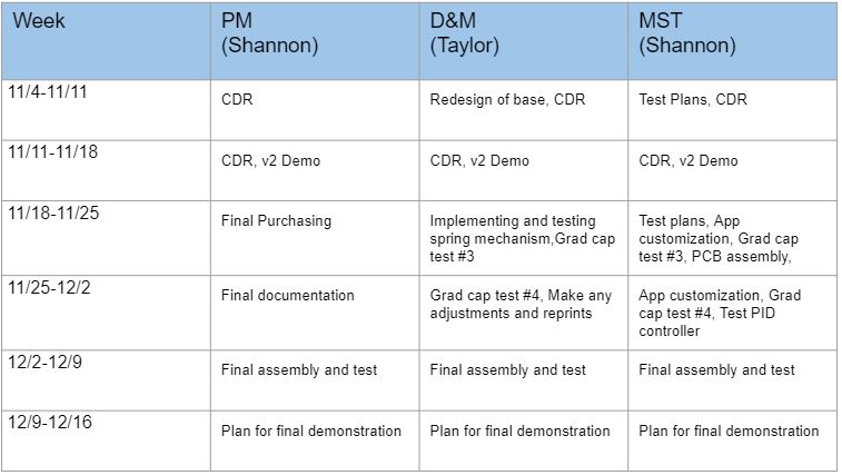
Schedule
Burndown and/or Percent Complete
Action Items and their percent complete can be viewed here.
Concept and Preliminary Design
Coming into this semester, the GradBot team knew we wanted to innovate and create something this course hadn’t seen or attempted before. With some inspiration from the ever popular Star Wars movies, the team came up with the idea to create a robot that was housed in a sphere and operated in a rolling motion much like the Astromech Droid, BB8. With some advice from Professor Hill, the BB8 style droid quickly morphed into a transparent bot with a Pyramid center piece to match the landmark at the Cal State Long Beach campus. Thus the first generation of GradBot was born.
Literature Review
This group knew we wanted to choose a project that had never been done before. We spent hours together researching and reading, trying to find anything that sparked our interest. It was our D&M, Taylor Manning, that first mentioned the idea of a remodeled version of the astro-mech droid BB8 from the Star Wars franchise. And the rest is history…
Design Innovation
With this project being the first generation of its kind, all designs are new and innovative. We worked hard to come up with a realistic style pyramid, a housing for the electronics, tires that were fitted to the contour of the sphere, and wheel hubs that would fit the motor shaft. The electronics housing and contoured tires were the most innovative ideas of the project as they played a key role in successful operation of the bot. The electronic housing effectively lowered the center of mass so that balance was significantly improved and the contoured tires allowed us to see increased efficiency in the robot’s ability to roll and be maneuvered using the Arxterra App.
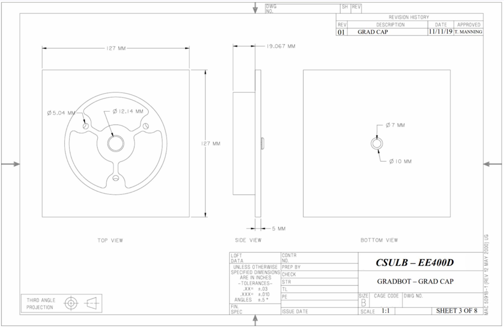
Below is a list of the drawings of any new models created for this generation of GradBot.
Conceptual Design / Proposed Solution
GradBot was originally designed to have two modes which would have been selected in the Arxterra App. One mode would work like a stereotypical controlled toy, using two digital toggles, one for forward and backward motion and one for left and right movement, giving the user the power to move the robot in any direction. The second mode would be a follower option. This option would have had the robot follow the user with about a 2 to 3 foot gap between them. The follower portion would be implemented using an accelerometer and gyroscope connected to a GPS module inside the robot which would then connect to the Blynk app and keep the robot within 3 feet of the user holding the phone.
You can read more about our conceptual design and proposed solutions here.
System Design / Final Design and Results
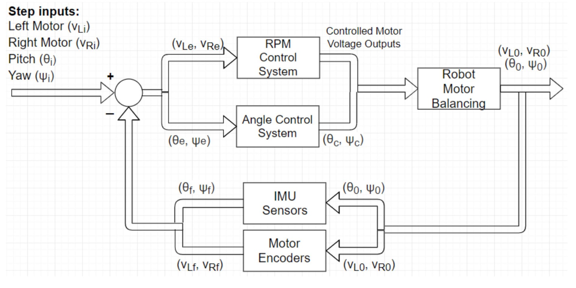
For the PID system to be implemented we needed an IMU which included an accelerometer and a gyroscope, as well as quadrature motor encoders. The encoders would gather measurements from the motors and the gyroscope would take measurements of the roll (wobble from left to right) and pitch (roll from front to back). All of this information would be plugged into a correction equation and sent back to the encoders and the board which should adjust the motors accordingly.
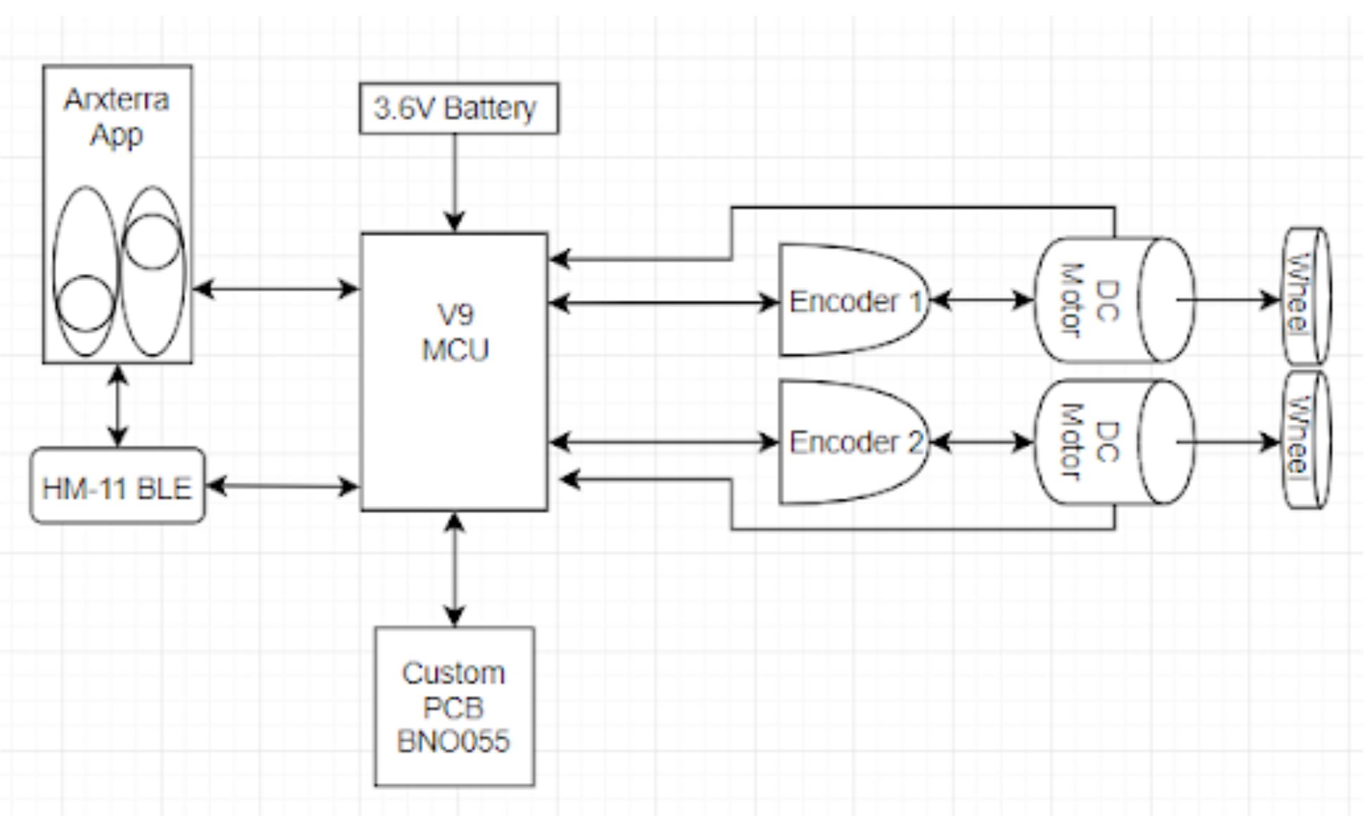
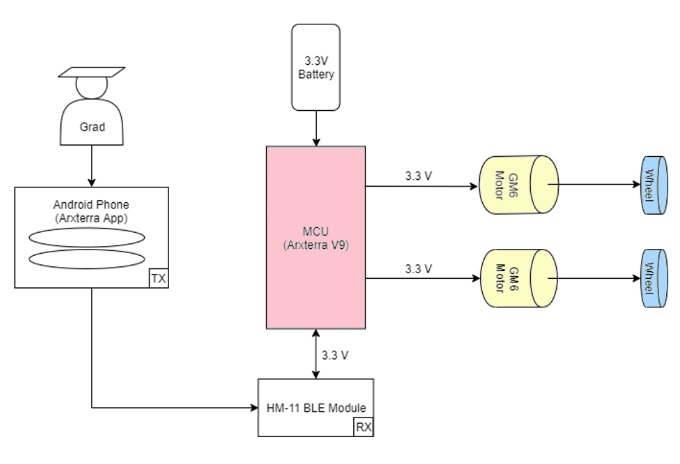
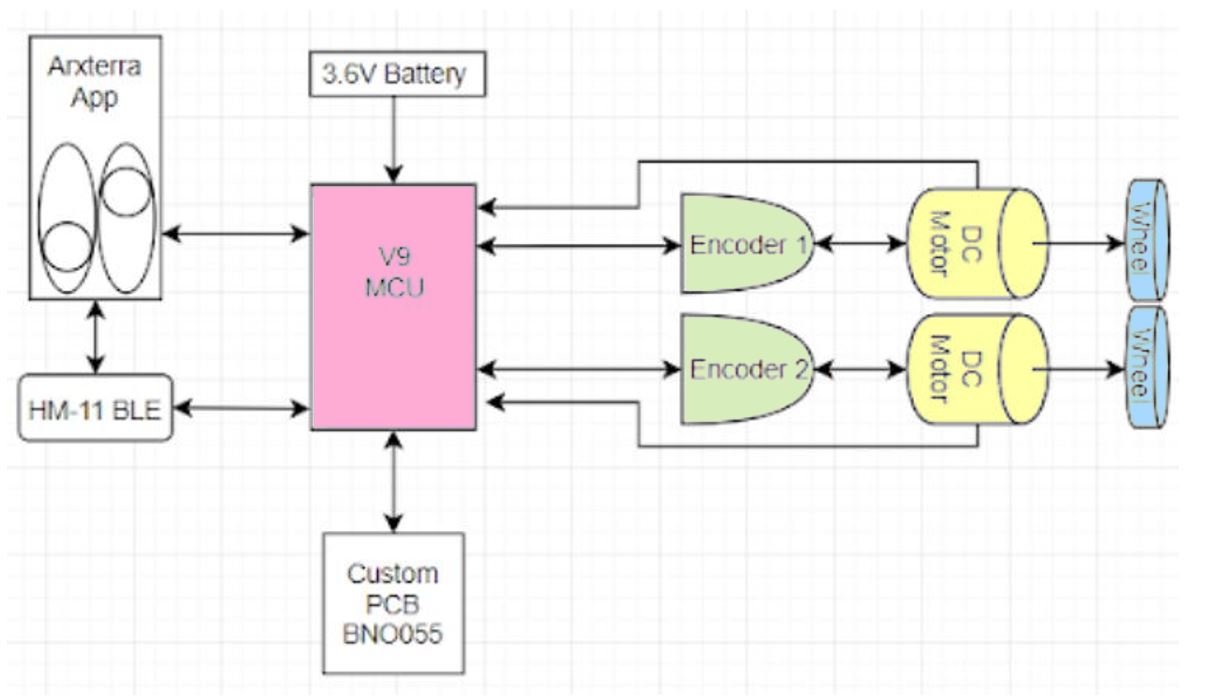
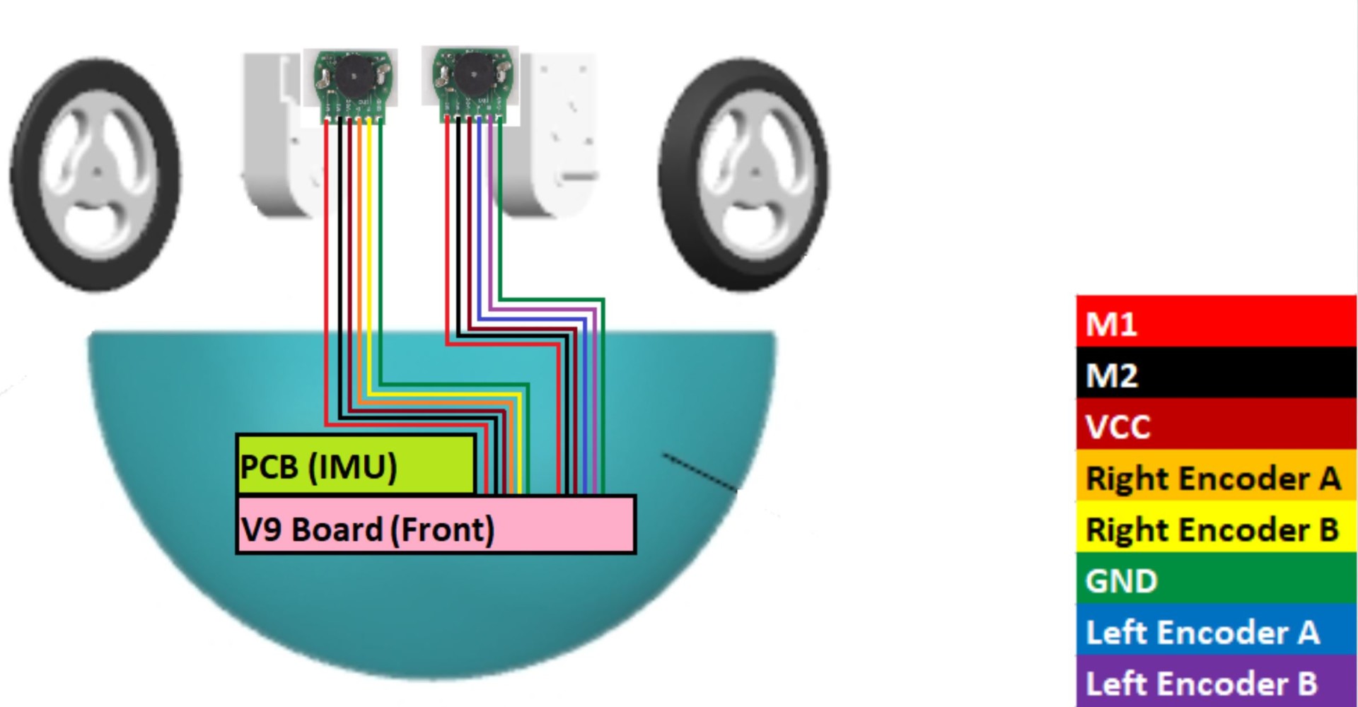
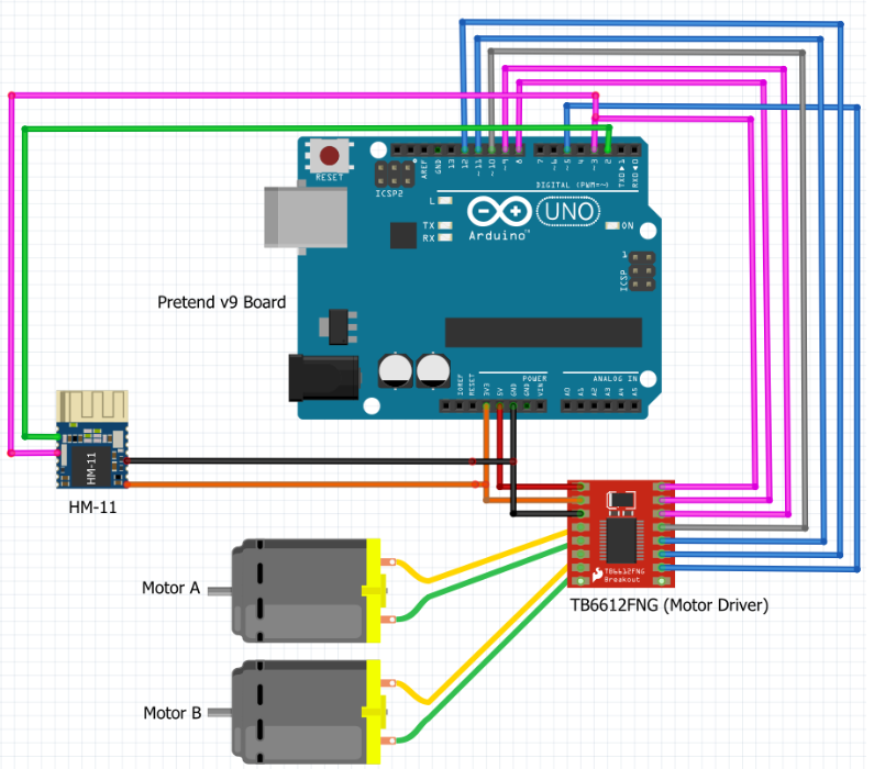
System Block Diagram
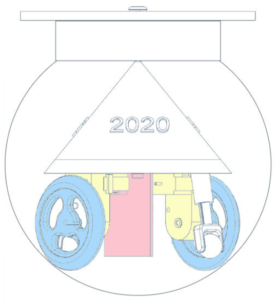
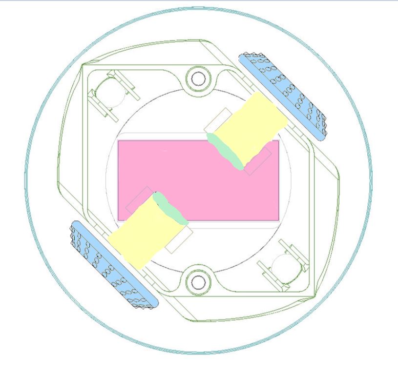
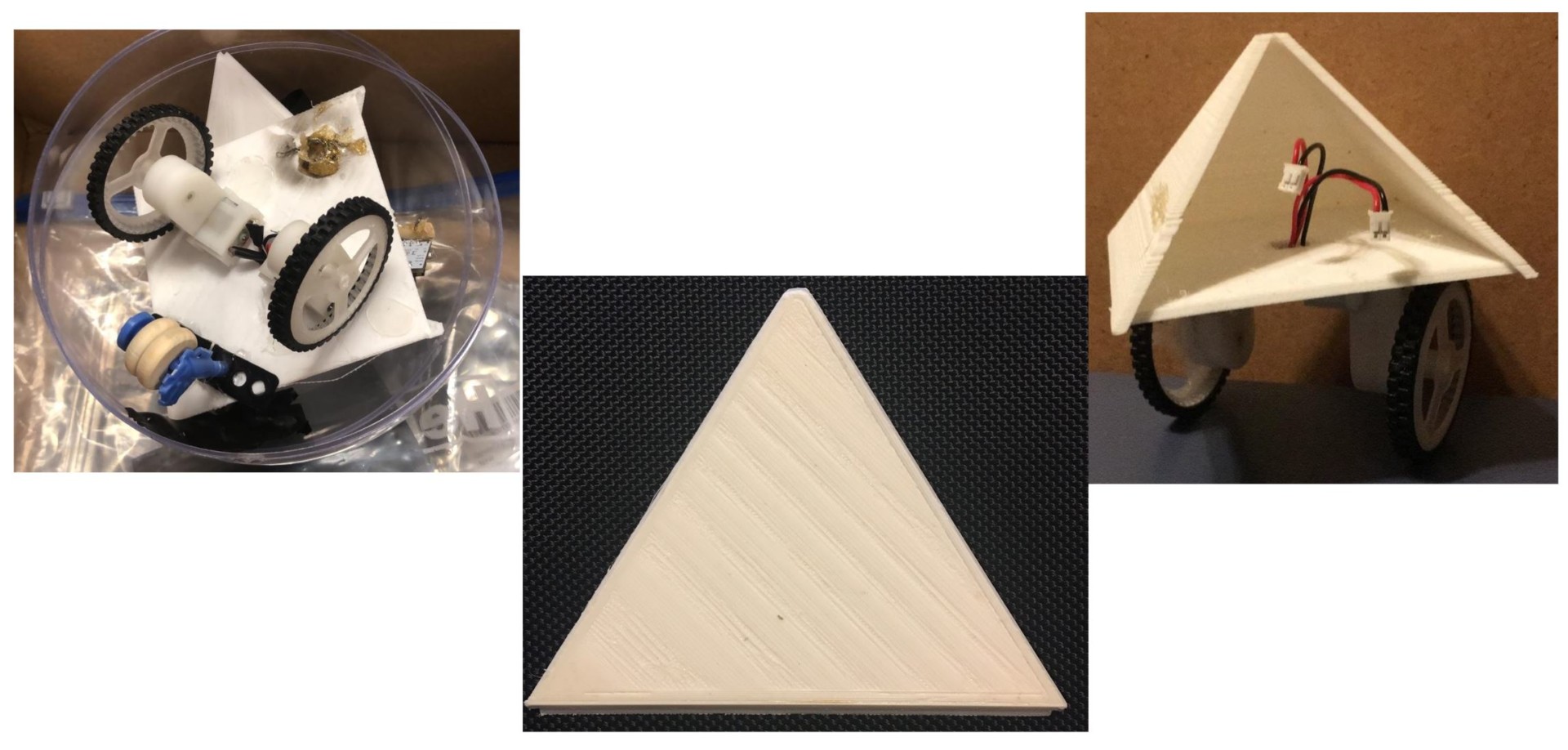
These images are color coded to emphasize tehe individual components. Pink for the v9 board, green for the motor encoders (which are not a part of version 1), yellow for the plastic gear motors, and blue for the wheels.
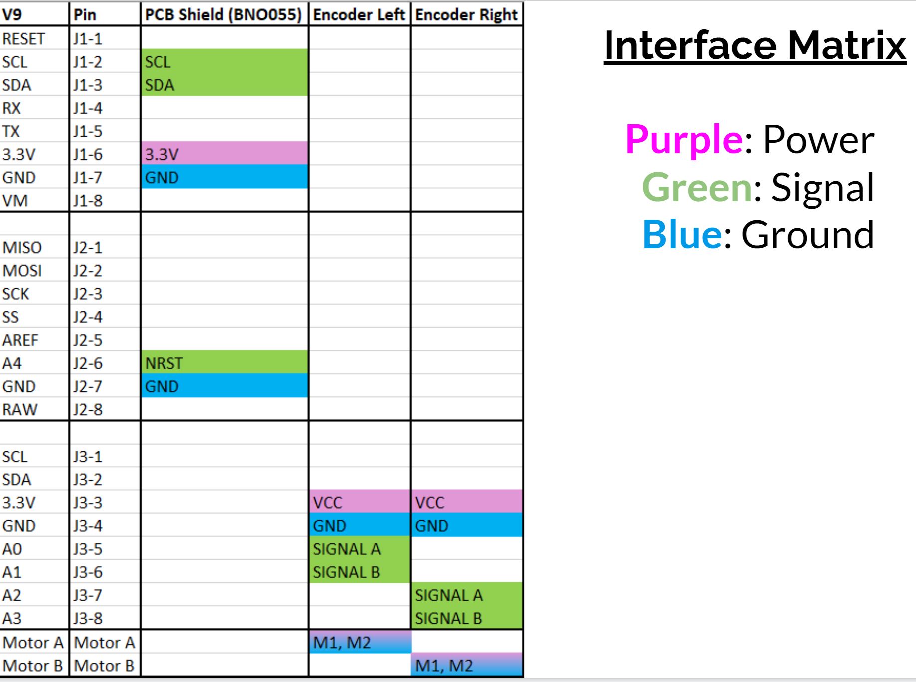
Interface Definition
Modeling/Experimental Results
Mortar Board Testing:
- A big part of this project was to create a graduation cap that would track on the top of the sphere and stay on GradBot during its travel across the stage. We intended to create a realistic looking mortar board so that the aesthetic portion would be successful, however we ran into several issues with the realistic version. We chose to 3D print our graduation cap for the robot, and although it felt light, it’s weight relative to the rest of the robot was far too heavy for the gm6 motors to overcome. Some movement would happen, but on most occasions the robot would stall and rock back and forth as the wheels tried to break the friction and clamping force caused by the magnets in the cap and the spindle inside the robot.
- To try and solve this issue, we modified the print so that unnecessary weight could be removed. While we did see some improvements, the cap was still too heavy and motion was poor.
- We then resorted to taking an old grad cap model and cutting out the center piece that held the magnet and discarding the rest of it. That way the only thing on the outer surface would be the magnet inlaid in a 3D printed part that matched the contour of the sphere. We also removed the bearings from the inner grad cap support spindle so that there would be nothing pinching the sphere and preventing it from rolling forward.
- This ended up working really well. The only issue was when the graduation cap rolled over the piece of tape holding the sphere together it lost its magnetic pull and fell of the sphere.
Electronic Housing Testing:
- We went through two different models of the electronic housing piece. Our first model was good in concept, but implementation proved more challenging than we predicted. We created a housing that would encase the wheels except for where they came into contact with the sphere. This made for a polished look for the internal robot, but assembly was rather difficult. The orientation of the pyramid and the wheels was too wide for the top opening of the electronic housing which made us have to assemble the wheels from the bottom. We deemed this a deal breaker for the final robot and brainstormed what would be best for GradBot.
- We decided to take our original design and just modify the corners where the wheels were located. Instead of encasing the entire thing, we left them fully exposed and printed them in black so they would blend a little better with the electronic housing piece. We were able to maintain a sleek and well put together look while also creating a robot that was easy to assemble and still house all the components we needed to.
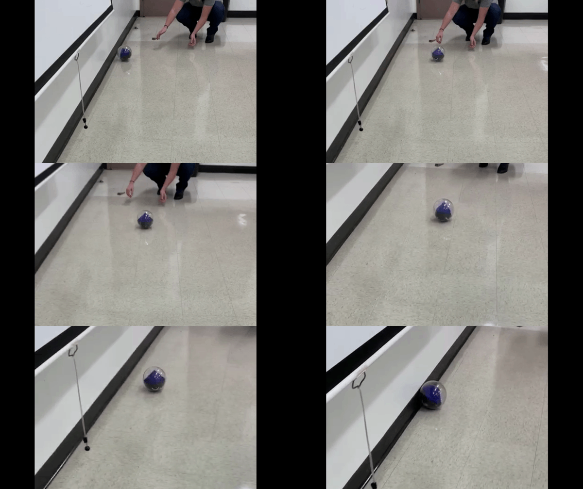
Click here to see the series of test videos.
| PART | PLANNED/COMPLETED | LINK TO BLOG POST |
| Pyramid | Implemented in final product. | https://www.arxterra.com/?p=152136&preview=true |
| Electronic Housing | Implemented in final product. | https://www.arxterra.com/?p=152136&preview=true |
| Grad Cap | Modifications made to implement in final product. | https://www.arxterra.com/?p=152136&preview=true |
| Grad Cap Support | Modifications made to implement in final product. | https://www.arxterra.com/?p=152136&preview=true |
| Motor Mounts | Not needed for final product. | https://www.arxterra.com/?p=152136&preview=true |
Electronic Design
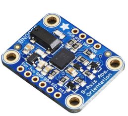
To allow our robot to be a follower we needed to implement an IMU along with the suggested PID. To test for what we needed we used the Adafruit BNO055 as seen below.
- From Adafruit
- Magnetometer, accelerometer, gyroscope
- Absolute Orientation (Euler Vector, 100Hz)
- Three axis orientation data based on a 360° sphere
- Voltage range (sensors): 2.4V – 3.6V
- I2C digital interface
- Total supply current in normal mode @ 3V: 12.3 mA
- Start-up time: 400 ms (on to config mode)
- POR time: 650 ms (reset to normal mode)
- Data rate tolerance 9DOF @100Hz output data rate
PCB Design
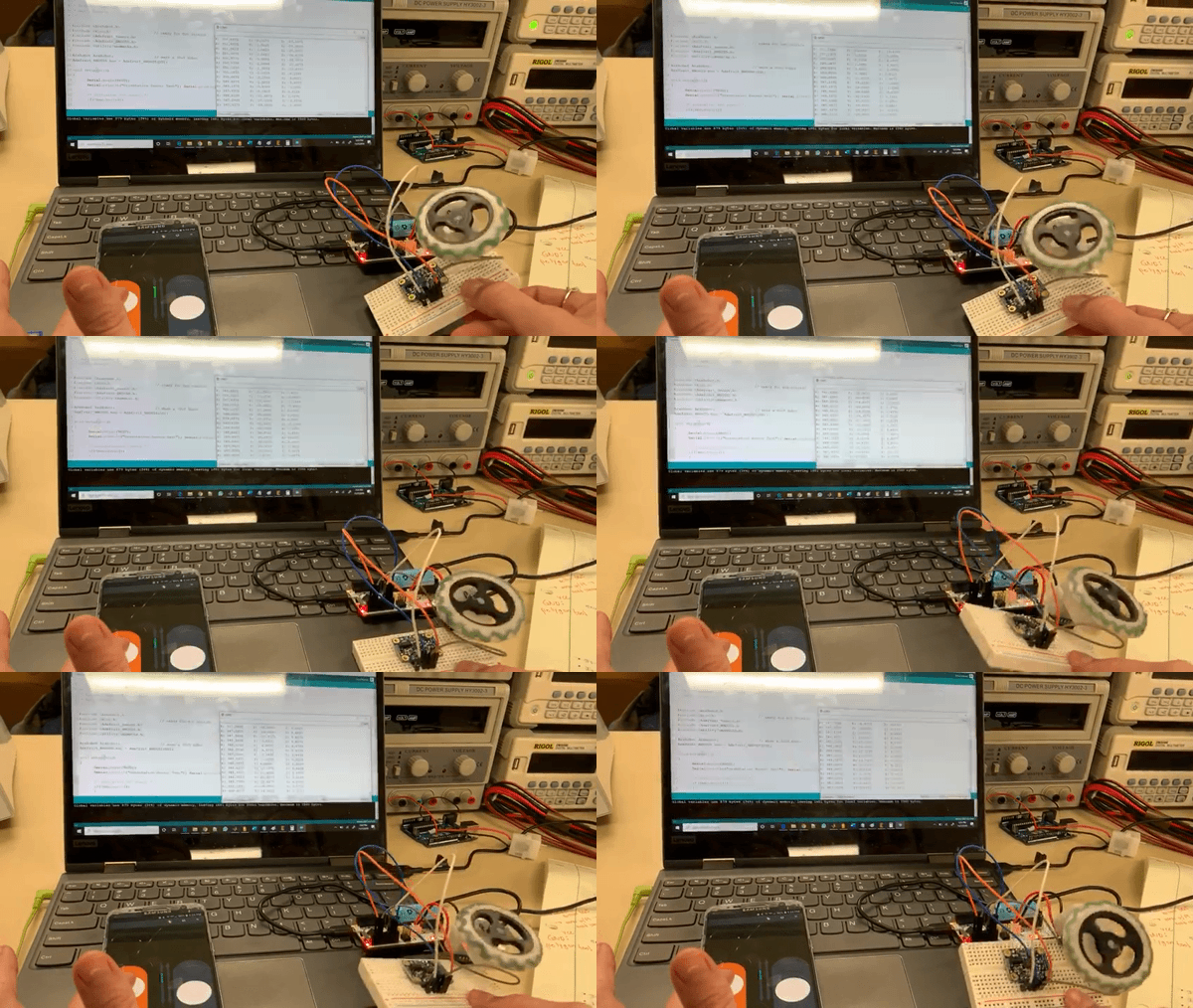
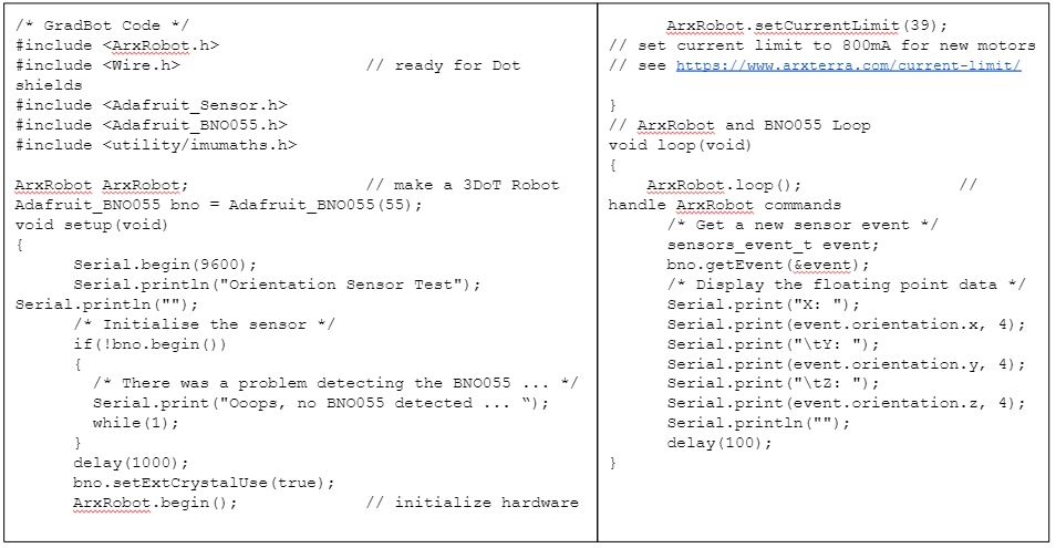
Below is the first and only breadboarding test we were able to accomplish. This includes the BNO055 (the accelerometer, gyroscope, and magnetometer) working with the motors on a single code uploaded to the v9 board.
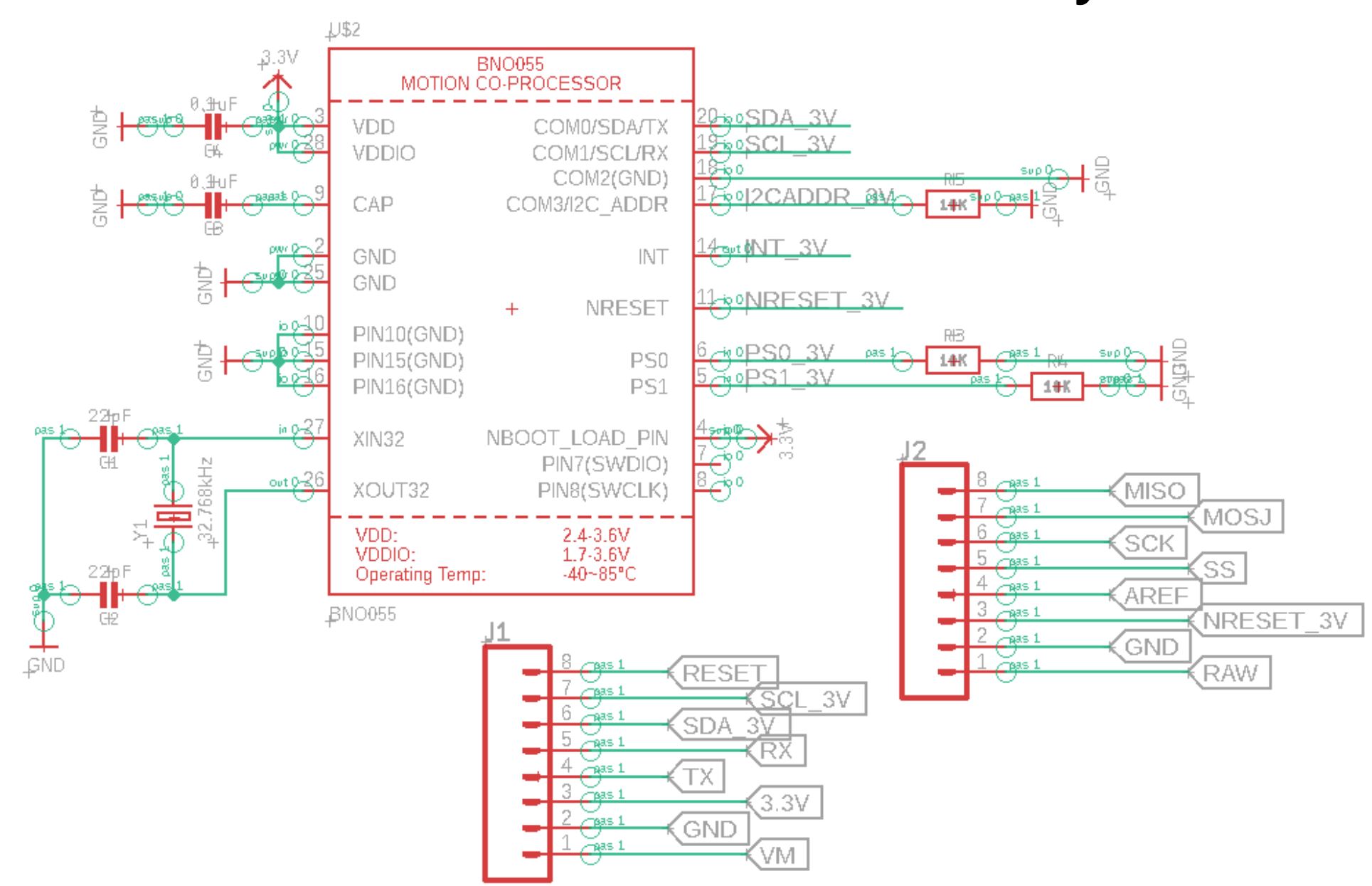
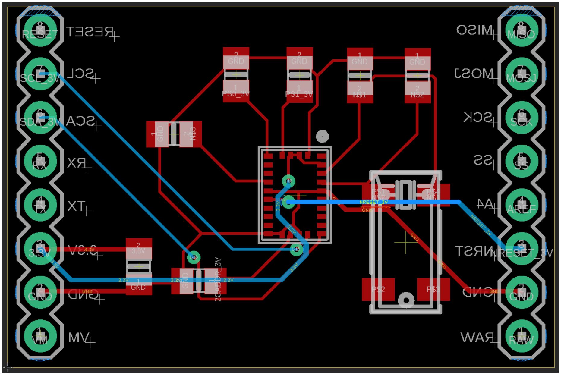
The PCB Schematic and layout combined all of the needed electrical components for the PID onto one board.
Firmware
- Step input: velocity from user in app
- Simultaneously:
- left encoder reads rpm (derived from voltage value)
- right encoder reads rpm (derived from voltage value)
- IMU reads pitch and yaw (Euler angle in degrees)
- Determine the offset of pitch and yaw from predetermined acceptable ranges (+- 10 degrees as a start)
- For angles out of range – convert into voltages for motors in control panel: tricky
- Left and right motor speeds are adjusted from a loop to balance the robot
Mechanical/Hardware Design
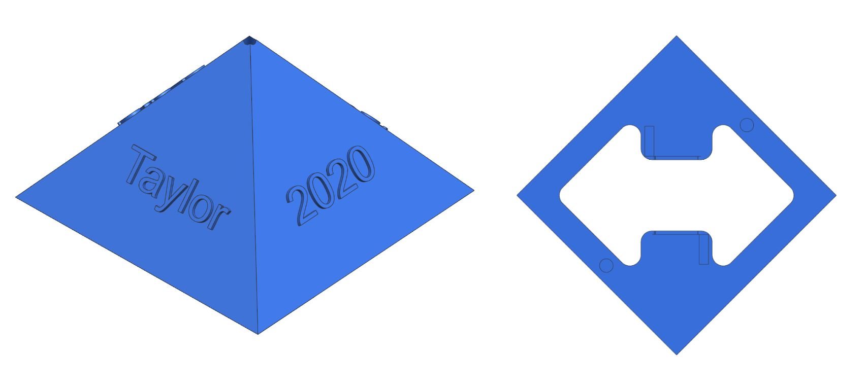
In our final iteration of the pyramid design, we no longer separated the pyramid in two. As you can see in Figures 1 and 2, the Pyramid is one piece with the center of the bottom cored out to lessen weight. The pattern seen arises from leaving surface area to mount the DC motors and inadvertently provides inner ledges in the pyramid to mount small electronics if deemed necessary. Otherwise now the spherical cover (which will be discussed later) will house a majority of the components so as to effectively drop the center of mass to the very bottom of the outer sphere. In this final iteration is also where we added the names of the group members and our graduating year for aesthetic flair.
This design was a challenging considering it had to match the bottom shape of the pyramid and then be contoured into the shape of a sphere. The next challenge was creating the places for the wheels and bearings to come through so they could aid in the balance of the pyramid and allow for it to still create forward motion. The final electronic housing featured a new sleek body design that keeps the wheels on the outside and could allow the assembly to more smoothly slide together. By creating these slices, we were able to reduce weight and keep it still looking aesthetically pleasing.
In the second iteration, we mimicked the graduation cap support so that it was just a 3-armed spindle with the same contour as the first iteration of the graduation cap. This significantly reduced the weight. We also reduced the weight by using either card stock or foam board for the mortarboard part of the cap and card stock for the cylindrical head piece. In preliminary testing of this new design, results were promising. Additional testing led us to use this same design shown in Figure 1, but removing the 3 arms sticking out and just working with the center circle piece. This further reduced the weight and tracked better on the outside of the sphere.
Designing the mechanism that would sit inside the sphere was very similar to the design of the graduation cap piece. We had to create a part that would match the center magnet in the cap and fit to the inner diameter of the sphere. With some advice, we were able to use the sphere model we already had to again make the proper contour to the part. By starting with an extruded triangle, we were able to overlay the sphere model onto it and use a subtract function to give us a perfect convexed shape to match the inner diameter of the sphere. From here we needed to design an insert for the magnet so this part could be used to magnetically hold the graduation cap normal to the top of the sphere. Bearings were set 120 degrees apart to match the graduation cap bearings and excess material was subtracted away to make the part lighter. A small hole was created in the center so a shaft could be placed in the center for attachment to the pyramid with a spring to create tension and downward force on the wheels. Additional testing was done by removing the bearings from this spindle and lowering it on the top of the sphere to help reduce friction during motion.
Originally, GradBot was going to utilize the tires/wheels that were provided in the 3dot kit for the sake of saving time and resources. However, we soon realized that using those tires would no longer be sufficient with only one edge of the tire making contact at any given time. This inhibits the motors ability to propel the robot forward efficiently and induces a wobble because the wheels grab the surface at different times. To mend this, we created a sturdier wheelbase that could better withstand the weight of the pyramid body, as well as created a slanted tire that will have more surface area in contact with the inner part of the sphere at any given time. We kept the wheel/tire approximately the same diameter as the ones from the 3 dot kit because the height matches well with where the pyramid needs to be positioned in the sphere. Instead we thickened the tire to accommodate for the angled slant and provide more surface area in contact with the sphere. The inner part of the wheel is hollow to create more traction when the weight of the robot is pushed down onto them.
Verification & Validation Test Plan
GradBot, a prototype toy for graduates aged 12+, will be demonstrated by having a graduate turn on the 3dot board, assemble all internal pieces, enclose the assembly within the sphere, place the mortarboard on top of the sphere and connect to the Arxterra App. From there, the graduate will place the robot at the beginning of the stage and be able to control GradBot to follow him across the entire length of the stage using the app’s controls. Once the crossing of the stage has been accomplished, GradBot has completed its intended mission and shall be removed from the stage by the graduate.
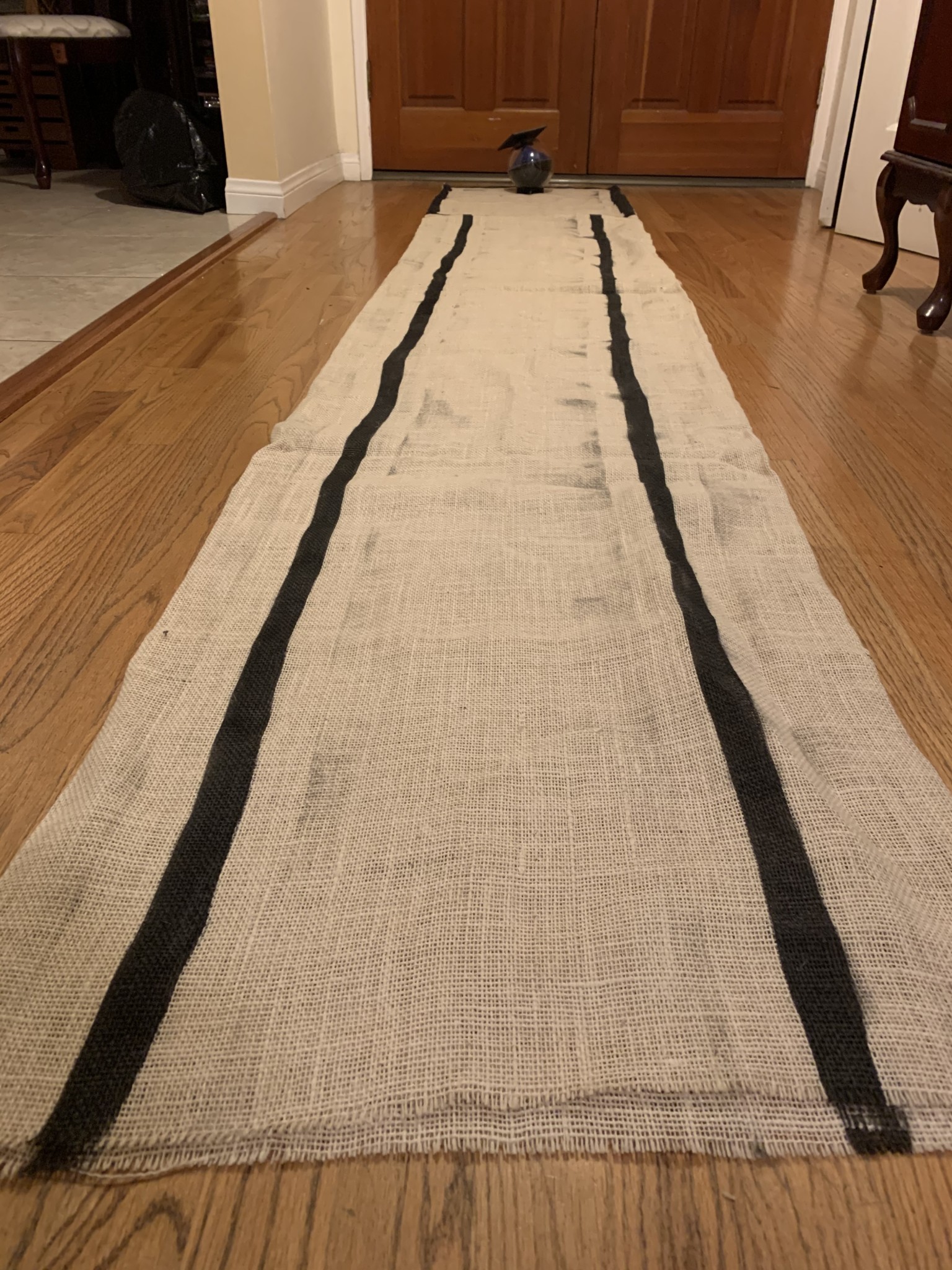
This being GradBot’s mission, our aim is to replicate the process that would be implemented by a graduate in a test environment to prove the working concept. To do this a test track will be laid on the ground with a black outlined guidelines. We have created a track that consists of a wide box to showcase the robot’s ability to be controlled in any X-Y direction as well as a 1.5ft wide by 7ft long track that will test for GradBot’s ability to roll in a straight line with ±6 inches of accuracy. This test will be run a second time to show it working with the graduation cap on.
You can find our verification and validation plan here.
Concluding Thoughts and Future Work
GradBot has been a humbling and very enlightening experience. Creating a project from scratch was far more challenging than we would have expected it to be, but at the same time it was exciting to start from the ground up and develop parts for this robot on our own. One of the biggest lessons learned is that this project will require skills that the Electrical Engineering program does not prepare you for properly, like 3D modeling. Starting from scratch meant extensive knowledge of 3D modeling was required, fortunately some work experience and the help of experienced mechanical engineers prepared me for the task. Another hard lesson learned was that being forced to start with a small model robot brings about more challenges than necessary because size constraints are going to be the biggest setback. This robot should have started out twice in size and future generations should have worked to decrease the size and functionality. In the future, I would have pushed to work with a 12 inch in diameter sphere so that larger motors, larger tires, and larger mechanisms could have been used to accomplish the necessary requirements. I would also in the future stay away from a transparent sphere and move toward an opaque sphere so that the internal mechanisms are not limited by an aesthetic constraint. All in all, we are pleased with the results that we got within the time frame of a semester and hope that future generations of GradBot exceed expectations and will one day see the actual graduation stage!
Please take a look at our Final Video explaining The Engineering Method and how we worked through it to get a finished product.
References/Resources
These are the starting resource files for the next generation of robots. All documentation shall be uploaded, linked to, and archived in to the Arxterra Google Drive. The “Resource” section includes links to the following material.
- Project Video YouTube or Vimeo link (see samples linked to here)
- CDR (PowerPoint, Prezi, or PDF)
- PDR (PowerPoint, Prezi, or PDF)
- Project Libre (with Excel Burndown file) or Microsoft Project File
- Verification and Validation Plan
- Solidworks File (zip folder) Linked to in Mechanical Design Post
- Fritzing Files Linked to in Electronics Design Blog Post
- EagleCAD files (zip folder) Linked to in Electronics Design Blog Post
- Arduino and/or C++ Code (zip folder) Linked to in Software Design Blog Post
- Other Application Programs (Processing, MatLab, LTSpice, Simulink, etc.)
- Complete Bill of Materials (BOM)
- Any other files you generated that you believe would help the next generation of students working on this project.

