MicroDozer (Goliath Generation 7)
Author/s: Deion Guillermo (PCB, Documentation), Moises Flores (Project Manager, Modeling), Jesus Rios (Mechanism, Software)
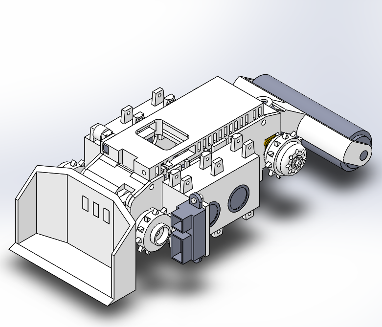
Figure 1: Final MicroDozer Assembly
Table of Contents
Executive Summary
Everyone has experienced somewhere in their household where misplaced items, dust, and/or trash has been found underneath furniture. However, it is not in your best interest to get down and reach underneath these pieces of furniture for health, sanitary or lack of motivation. MicroDozer is a small robot derived from a long line of previous Goliath robot generations that can fit within cramped spaces such as underneath or behind furniture. Using remote controlled navigation, the robot can be manually driven to collect items and clean dust in these hard to reach areas.
Program and Project Objectives
The MicroDozer is a 3-D printed robot based on the Arxterra line of 3DoT Goliath robots. This robot will take advantage of the small scale of the Goliath robots to navigate underneath household furniture. When underneath the furniture, the MicroDozer can push and lift small, misplaced objects with its dozer blade, much like a bulldozer. With ArxRobotApp’s camera integration, the MicroDozer provides live feed of the robot’s view allowing for ease of navigation. The robot provides autonomous functions as well; it has the ability to escape out from underneath furniture and it can reduce its speed when near narrow spaces.
Mission Profile
The robot shall be driven manually through remote controls that provide the option to use a live camera feed. Through these controls, the robot will have the ability to remove various small, light objects from underneath the width of a lab table, chair, and instructor’s desk within the VEC-415 Lab. In the event the robot is lost beneath a piece of furniture, an escape command can allow the robot to autonomously follow a bright light source to lead itself out to an open area to be recovered. During this escape sequence, the robot will also have the ability to avoid a head on collision with large obstacles.
Project Features
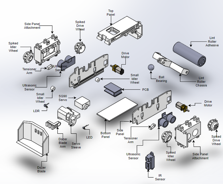
Figure 2: MicroDozer V3 Annotated Exploded View
The MicroDozer innovates from the latest generation of the Goliath series of robots. The MicroDozer includes a multitude of different additions to the E-racer model in order to accomplish tasks such as pushing small scale objects using a dozer blade located at the forefront of the robot. This dozer blade is capable of lifting the blade up and down, allowing for further interaction between the robot and its surroundings. Other features include an IR sensor and photoresistor that work in tandem to provide an autonomous escape command. Lastly, as the robot approaches a cramped area, the ultrasonic sensors automatically reduce the maximum speed of the robot in order for the user to perform more accurate movements.
Requirements
The MicroDozer will follow the constraints imposed by the Robot Company and the Project Stakeholders. The following sections describe the University, environmental, health and safety standards that apply to the product, as well as the development of this project.
Engineering Standards and Constraints
Applicable Engineering Standards
Constraints:
- All 3DoT robots shall incorporate the 3DoT v8 or later series of boards.
- Software shall be written in the Arduino De facto Standard scripting language and/or using the GCC C++ programming language, which is implements the ISO C++ standard (ISO/IEC 14882:1998) published in 1998, and the 2011 and 2014 revisions.
- All 3DoT robots shall be in compliance with the 3DoT Command and Telemetry Packet specification.
- All 3DoT robots shall be controlled via Bluetooth 4.0 in compliance with the Bluetooth Special Interest Group (SIG) Standard (supersedes IEEE 802.15.1).
- MicroDozer shall not exceed a cost of $350.
Standards:
- IEEE 29148-2018 – ISO/IEC/IEEE Approved Draft International Standard – Systems and Software Engineering — Life Cycle Processes –Requirements Engineering.
- Bluetooth Special Interest Group (SIG) Standard (supersedes IEEE 802.15.1)
- C++ standard (ISO/IEC 14882:1998)
- Federal Communications Commission (FCC) Relevant standards for a product implementing a 2.4GHz radio, FCC Intentional Radiators (Radio) Part 15C, and Unintentional Radiators FCC Part 15B for CPU, memories etc.
- NXP Semiconductor, UM10204, I2C-bus specification and user manual.
- ATmega16U4/ATmega32U4, 8-bit Microcontroller with 16/32K bytes of ISP Flash and USB Controller datasheet section datasheet, Section 18, USART.
- USB 2.0 Specification released on April 27, 2000, usb_20_20180904.zip
- Motorola’s SPI Block Guide V03.06
Environmental, Health, and Safety (EH&S) Standards
- CSULB College of Engineering (COE) Safety Resources.
- CSULB Environmental Health & Safety (EH&S)
- IEEE National Electrical Safety Code (NESC)
- NCEES Fundamental Handbook (FE) Reference Handbook
- ASTM F963-17, The Standard Consumer Safety Specification for Toy Safety
Program Level 1 Requirements
1.3 The robot’s locomotion will be manually and remotely controlled through the ArxRobot app and control panel.
1.6 The robot shall successfully collect dust off of carpeting, linoleum, and wooden floors.
1.9 The robot shall be able to be retrieved from underneath furniture without requiring some external object (i.e. a broom to reach underneath) having to reach more than 10cm underneath furniture.
1.10 The robot shall use a custom PCB intended to control a flashlight, escape feature, and limit the bot’s maximum movement speed.
1.12 The robot shall have gone through its verification test plan by the end of December 17, 2019.
1.13 The robot shall be constrained to a cost not exceeding $350.
Project Level 1 Functional Requirements
1.1 The robot shall push objects less than 75x75mm and up to 300 grams out from underneath and behind furniture with clearances of 110x110mm.
1.2 The robot shall be able to traverse obstacles up to 7mm in height.
1.4 The robot shall provide the option to display a live camera feed from its front.
1.5 The robot shall have the option to illuminate its forward path with a lighting system with a diameter less than 35mm.
1.7 The robot’s driving shall be accomplished through using no more than two drive motors.
1.8 The robot shall be able to avoid crashing into obstructions weighing more than 5kg.
1.11 The robot should use a custom IMU PCB to control its automated movements given that the IMU is functional and able to be implemented on the day of demonstration.
System/Subsystem/Specifications Level 2 Requirements
2.1.1-a The base robot without its lint roller will be built within the size of a 4in x 7in x 4in (10.16cm x 17.78cm x 10.16cm) frame.
2.1.1-b The non-metal parts and chassis will be 3D printed using ABS in order to generate parts that function at its small size.
2.1.1-c The robot shall use a U-blade design to flip or push objects over 7mm obstacles (such as wires).
2.1.2-a The robot shall lift its blade from 0° to 35° relative to its resting position using no more than one SG90 servo motor to avoid snagging on immovable obstacles low to the ground.
2.1.2-b The robot shall use rubber treads to traverse over objects of up to 7mm in height.
2.1.3 The robot shall use the 3DoT V9 board and ArxRobot app custom commands to handle the driving, servo lifting, lighting, and escape feature.
2.1.4 The robot shall have the option to use the ArxRobot Control Panel to control its movement while using the robot’s phone camera functionality.
2.1.5 The robot shall use a flashlight attachment made of 1 white LED that can vary between light levels and turned on/off.
2.1.6 The robot will use a custom lint roller in order to pick up dust, lint, and short hairs.
2.1.7 The robot will use no more than two 1.2kg*cm torque Wal front motors to allow movement.
2.1.8 The robot shall use an IR sensor to detect distance from an immovable obstacle as prevention for bumping into walls/furniture legs 3cm from the front of the blade.
2.1.9 The robot shall utilize an escape feature using an LDR, IR, and ultrasonic sensors to navigate from underneath dark furniture to where a beacon of light (i.e. a phone flashlight) is directing it.
2.1.10-a The robot shall use a photo-detection circuit to escape from underneath furniture within 30 seconds of instruction whenever necessary.
2.1.10-b Given that the inertial measurement unit is fully functional, the robot should use the IMU to track its movement and make sure that it is moving in the correct direction of its targeted light when escaping from underneath furniture.
2.1.11 The robot shall use a pair of ultrasonic sensors, one at each of its left and right sides, to detect obstacles within 10cm of distance and be able to limit its maximum travel speed down to 70%.
2.1.12 The robot shall utilize the provided verification test plan template to confirm that the tests were indeed completed.
Allocated Requirements / System Resource Reports
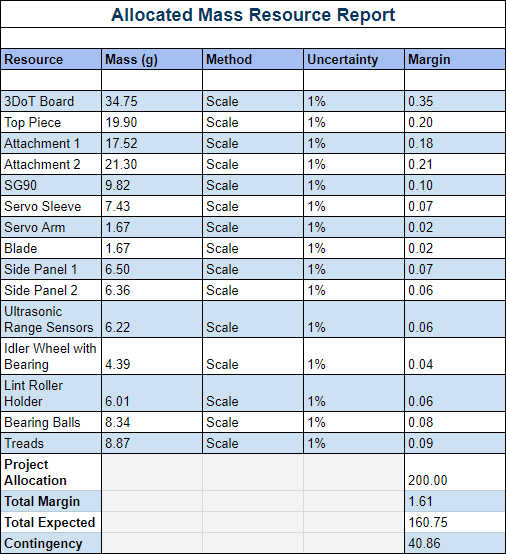
Figure 3: Allocated Mass Resource Report
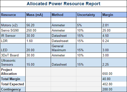
Figure 4: Allocated Power Resource Report
Project Report
The project report contains the Work Breakdown Structure, Product Breakdown Structure, Cost Report, and Schedule. This section documents the organization within the team in order to stay on track, and stay on task in a timely matter.
Project WBS and PBS
The Work Breakdown Schedule (WBS) organizes the various tasks each individual team member will complete in order for the project to succeed.
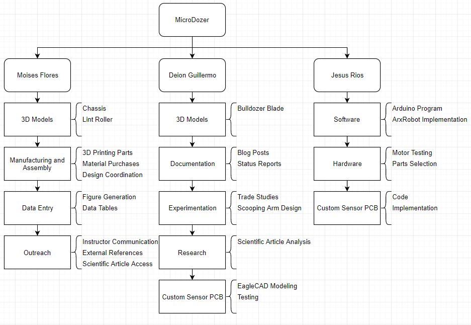
Figure 5: Work Breakdown Structure
The Product Breakdown Structure (PBS) displays the deliverables of the project that each individual member will be responsible for.
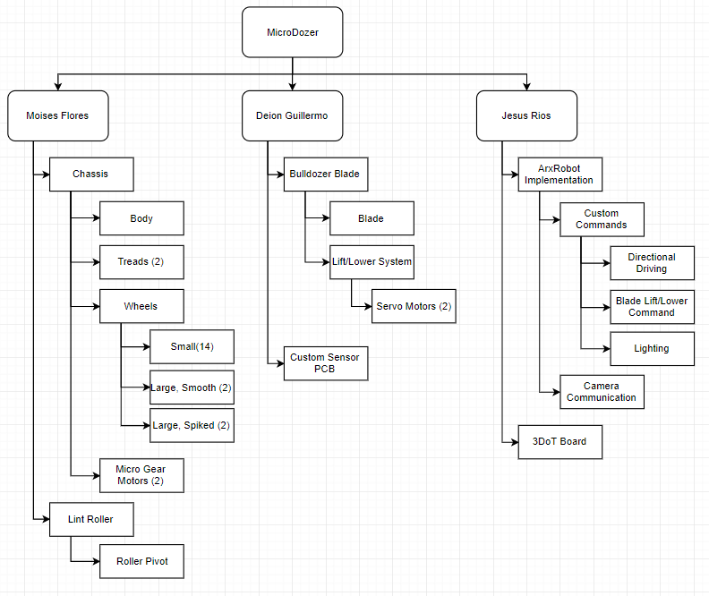
Figure 6: Product Breakdown Structure
Cost
The project Cost Report is shown below. The project had a budget of $250 when the team was still working towards MicroTug. However, the project budget increased to $350 when the project overhauled into MicroDozer. Luckily, some costs were kept at a minimum as some components were able to be re-purposed in the new project. Unfortunately, our biggest expense from MicroTug – the Dow Corning Sylgard 170 adhesive material – was denied from refunding and return.
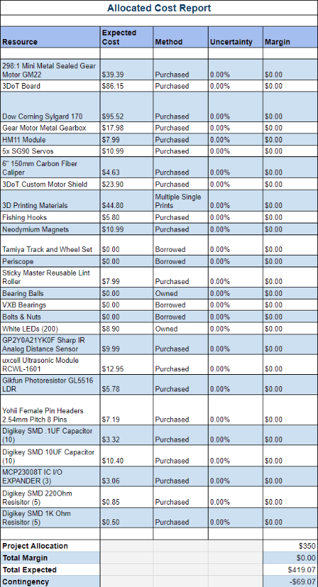
Figure 7: Cost Report
Schedule
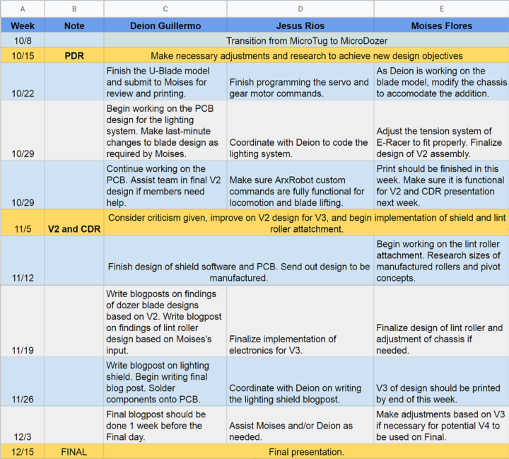
Figure 8: Project Schedule
Concept and Preliminary Design
The 7th Generation of Goliath aims to improve on the structural issues of the previous generations while maintaining the same compact size the Goliath is known for. Further, structural design is adjusted to accommodate the additional sensors and components in order to increase the flexibility of the robot’s functionality.
Literature Review
Before the team worked on MicroDozer, the team had instead been working on another project – MicroTug. This bot was inspired from the MicroTugs from University of Stanford’s Biomedical and Dextrous Manipulation Laboratory (BDML). This particular robot is an extremely small robot, measuring within a 25mm cube and only weighing in at about 12 grams. However, thanks to a special adhesive structure located on the underside of the robot, it has the ability to pull a load about 2,000 times its own weight.
Inspired by this bot, the team set out to create an upscaled version of this robot, utilizing the 3DoT board. However, complications arose in the development of this project, and a project overhaul was required. Through the use of Duncker Diagrams, the idea of “if we pull” versus “if we don’t pull”. That followed into the idea of “push not pull”. Thus, the project was overhauled into MicroDozer, a small robot that can push small objects out of hard to reach places.
Design Innovation
As the new design needed a small robot capable of navigating underneath and behind various furniture around a typical household, the Goliath showed itself as the best solution. Through the various generations, the design of Goliath has steadily been compressed as much as possible, allowing for an extremely compact robot. Our team plans to utilize this compact size in order to navigate the necessary environment. Alongside the small size, additional sensors and structures will be added to assist in its ability to navigate as well as interact with foreign objects commonly found beneath household furniture.
Conceptual Design / Proposed Solution
With the project overhaul, a priority for the team was to find a project that could be feasible in the time left in the semester. Initially, the bot merely had the basic functions to push with a dozer blade as well as include a vision system utilizing both the arxterra app’s camera functionality and a flashlight for the dark environments the robot will find itself in frequently. As the semester went on, the team put together increasing levels of complexity to the robot to cover more situations the robot may encounter.
System Design / Final Design and Results
The increasing level of difficulty lead to the attachment of the photoresistor and IR sensor in working in conjunction to create an autonomous escape command. Further, the team included ultrasonic sensors to decrease the maximum speed of the robot while near obstacles in order to make more precise movements. Details of the changes to the mechanical, software and firmware due to these additions are described in the following sections.
System Block Diagram
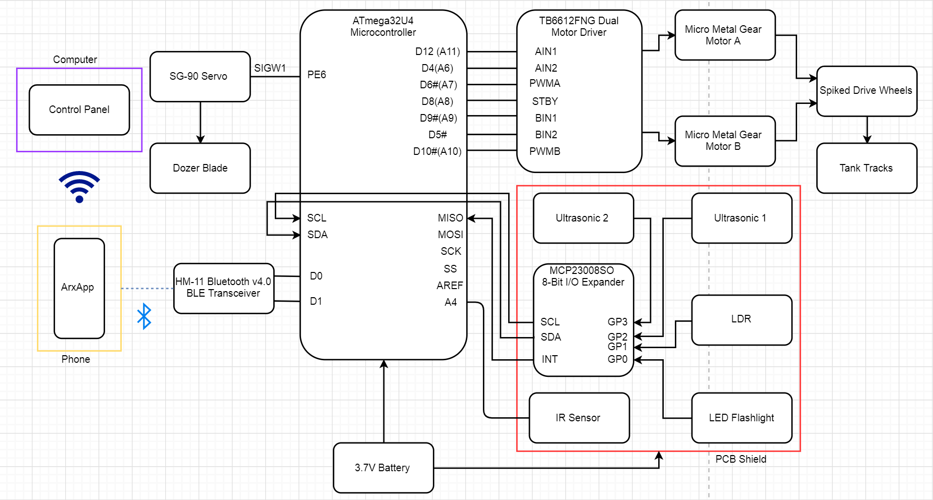
Figure 9: System Block Diagram
Interface Definition
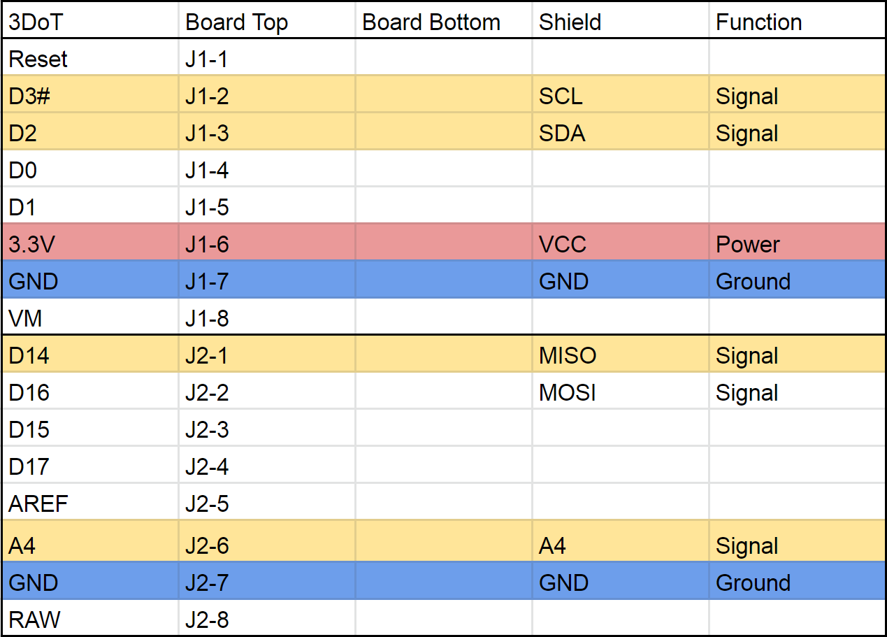
Figure 10: Interface Matrix
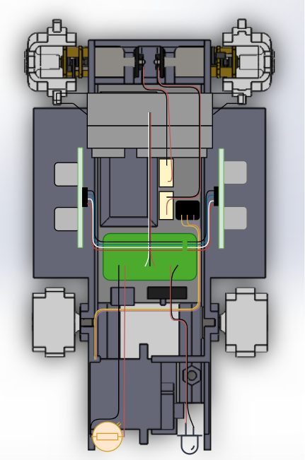
Figure 11: Cabling Tree
Modeling/Experimental Results
For the previous project, a trade-off study was performed to decide which anchoring system would be best. In this test, we compared the performance of an array of fishing hooks, neodymium magnets, as well as Sharkskin. For further information please read the Anchoring System Trade-off Study Blog Post.
Mission Command and Control
3DoT Robots
| Hardware | Software |
| Personal Computer | Arxterra Control Panel |
| Smartphone | ArxRobot App |
| 3DoT Board | Arduino and Robot3DoT Library |
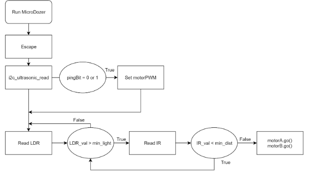
Figure 12: Firmware Block Diagram
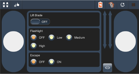
Figure 13: ArxRobotApp Interface
Electronic Design
PCB Design
The PCB design is based heavily on accommodating for the additional components need to perform various tasks outside the main function of the robot. These include communication between the IR sensor, the ultrasonic sensors, the photoresistor, as well as the LED flashlight. For more information, please read the PCB Custom Shield Blog Post.
In addition to the MicroDozer’s sensor PCB, another PCB is attached to the MicroDozer. This PCB is an Initial Measurement Unit (IMU) designed and manufactured somewhat independently from the MicroDozer team by Clare Lahey. For more information, please refer to the IMU Blog Post.
If the optional IMU is used, the coordinates of the robot in the pitch, yaw, and roll directions can be displayed on the Arxterra app, as seen here.
Firmware
Fall 2019 MicroDozer intended to have a servo lift arm and autonomous “escape” feature. Multiple input and output ports were to be used to add extra features such as LED lights, IR sensors, Ultrasonic sensors, and Photoresistor. Click here for more info.
Mechanical/Hardware Design
The mechanical design of MicroDozer has largely been influenced by two main sources: the previous generation E-racer as well as input from Jeff Gomes. As a starting point, the team utilized the design provided by E-racer. However, upon meeting with Jeff, his input provided many possible improvements to Goliath’s design. For a more in-depth information about this topic, please refer to the Blog Post: Mechanical Design.
Verification & Validation Test Plan
The Validation and Verification test plan provides the guidelines against which the robot will be tested. It prepares a mission in which the robot will perform, and various test cases will verify whether or not requirements have been met.
The detailed test plan can be found here.
Concluding Thoughts and Future Work
The beginning of the project is incredibly important. When making the big decision of choosing a project a the beginning of a semester, it is fine to be optimistic. However, keeping the project cohesive – considering the project’s mission, objectives, use-case, complexity, and possibility of completion within a time frame of a single semester. Our biggest roadblock may have been this, which led to the project’s overhaul halfway through the semester. With almost an entirely new project and only half the time to complete it, the path to success became extremely difficult. If we had started with MicroDozer from the very beginning, the results may have been much better.
Besides the time constraints, the MicroDozer robot can definitely be improved upon. For example, the structural design can still be improved upon, especially with the input from Jeff Gomes, who already has his own iteration of the Goliath robot. In our case, the mechanical design can be adjusted such that the assembly of the robot is much more streamlined. Another structural change would be the tensioning system. MicroDozer lacks any kind of locking mechanism for the tensioning system, even if the idea was innovative. The hardware and firmware can also be explored further, as the MicroDozer team was unfortunately unable to communicate with the GPIO expander properly. If that is possible, then the escape command and automatic speed limiters may be functional as well.
References/Resources
These are the starting resource files for the next generation of robots. All documentation shall be uploaded, linked to, and archived in to the Arxterra Google Drive. The “Resource” section includes links to the following material.
- Project Video YouTube
- CDR (PowerPoint Presentation)
- PDR (PowerPoint Presentation)
- Project Libre (with Excel Burndown file) or Microsoft Project File
- Verification and Validation Plan
- Solidworks File (zip folder) Linked to in Mechanical Design Post
- Fritzing Files Linked to in Electronics Design Blog Post
- EagleCAD files (zip folder) Linked to in Electronics Design Blog Post
- Arduino (zip folder) Linked to in Software Design Blog Post
- EagleCAD (Processing, MatLab, LTSpice, Simulink, etc.)
- Complete Bill of Materials (BOM) with vendor names for both mechanical and electrical parts. Create in Excel or your favorite spreadsheet application. Upload as PDF. Do not post receipts, which may contain sensitive information including your name, address, and credit card information. Do not simply draw a black box over material in Word. Hackers can easily remove!
- Any other files you generated that you believe would help the next generation of students working on this project.