MicroDozer Fall 2019: Mechanical Design
Author: Moises Flores (Project Manager/3D Modeling)
Table of Contents
Introduction
This iteration of Goliath has had significantly different goals than those of previous generations. Whereas previous generations focused on tasks like improving accuracy as a scale model or automated line-following, this project focused on manually-controlled trash cleanup. Through this goal, the mechanical design and models used for the project required significant changes.
In the case of this project, the Version 1 (V1) was a reprint of E-Racer’s most recent iteration, which was not functional. This caused a redesign of many of E-Racer’s parts, namely its top and side panels. V2 was an extension of V1 that utilized an extremely rough pocket to house the SG90 used for the bulldozer blade. This version was fully serviceable and used in the Critical Design Review’s V2 demonstration. V3 was the final design used in verification and validation, which was redesigned ground-up due to difficulties to be described later in this post.
Evolution from E-Racer – V2
As one would assume, the current generation of any design would take inspiration from one or several of its previous iterations. In the case of MicroDozer, the V1 design was simply a reprint of the most recently available models used by E-racer.
More information on E-Racer’s mechanical design can be found here.
MicroDozer V2 had to be designed in 2.5 weeks after PDR to be ready for CDR. The three main changes made to V2 were as follows:
1. Bulldozer Blade
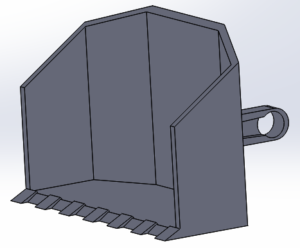
The key concept followed behind this iteration was following the design of a miniature bulldozer used for low-clearance furniture. As such, the design required a bulldozer blade to be designed. Deion Guillermo had modeled the blade, which followed a U-blade design for pushing objects large distances.
The blade was designed to have an arm that reaches into the chassis of the robot with an imprint for a one-sided servo horn to attach to the SG90 using a screw.
2. Blade-Lifting Mechanism
Expected from µDozer was the capability to raise and lower its blade, as is expected from an industrial bulldozer. To fulfill this requirement, an Sg90 servo was selected because of its cheapness, availability, and torque of 1.2kg/cm. This meant that at a distance of 4 cm, the servo would be rated to lift a load of 300 grams.
- To avoid the chances of stalling the servo or burning it out from extensive load, the team decided that the robot should not be expected to lift anything greater than 200 grams. To avoid making the center of mass to far from the servo’s shaft, the blade was designed with shallow depth, which coincides with the function of pushing only small, lightweight objects.
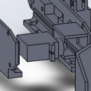
After having established the need for an SG90, accommodations had to be made for being able to hold the servo securely in place while it lifts and lowers. Due to time constraints before the V2 demo, a simple sling and cavity combination was designed into the two side panels of the chassis. Unfortunately, too much room for error was allowed in the sling, and the servo was able to shift around while in the chassis. If one were to wedge a small object, such as a folded piece of paper, between the servo and the sleeve, however, the lifting mechanism would work as intended. This would be a major fix needed in the next iteration of µDozer’s design.
3. Expanded Chassis and Parts
Expanded chassis and parts – The original chassis of E-Racer could no longer house all of the components required for µDozer. This resulted in the extension of the chassis by 32mm lengthwise. The chassis was only expanded by its length and not its height because the focus of its dimensional limitations, 4x7x4 inches, was intended to limit its height and width. The height would allow a greater range of under-the-couch furniture clearance, and width would allow a greater range of behind-the-shelf clearance; the length was less of an issue, as the robot was capable of nearly turning without displacing itself due to the use of treads and tread controls.
A significant design flaw of E-Racer was the fact that the tension system was sized incorrectly. When assembled in SOLIDWORKS, the model may seem to be fine to a beginner because the parts all fit together without intersection when using the assembly function. However, there was no consideration of expansion/shrinking in the process of 3D printing. Thus, the “tensioner” part inserted into the side panels of V1 were too large to fit. Changes to the model’s dimensions were made to accommodate proper fitting.
E-Racer final model files can be found here.
Aside from these three changes, the models and prints for V2 were kept the same as V1.
Race to the Finish – V3
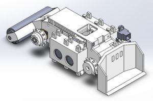
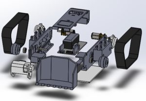
Figure 5: Final assembly model of V3, excluding treads and superlative amount of small idler wheels for easier viewing.
After having completed V2 and confirming that it was functional upon the V2 demonstration after CDR, the models for V3 began being edited immediately. A significant number of changes were made to the chassis and attaching parts, which can be divided into two sections: improving the chassis and accommodations for the custom shield. All changes made from this point onward were made while keeping in mind the advice given by Jeff Gomes, a mechanical engineer who is a part of the ArxTerra team.
1. Initial Chassis Improvements from V2
Note: Although many of the models are visually similar to that of V2 and E-Racer, all models that are not the small idler wheels were created from the ground up. Too many difficulties arose from trying to use the original E-Racer models due to abstract dimensions and dependent sketches/features, so new models were made based off of general measurements of E-Racer parts
Servo Sleeve and Bulldozer Arm
One of the first things that had to be improved was the servo sling from the V2 iteration. As mentioned earlier, the servo sling was too loose for the SG90. The sling’s design was quickly recognized to be undesirable for a final product, so it was scrapped and replaced with a new design for a servo sleeve that was detachable from the chassis.
The sleeve was designed as a derivation of the door panel from E-Racer, as it was a hinge-based door hatch for easy access to the 3DoT. A flaw with the V2 iteration was that it was a static sling and prevented the 3DoT from being inserted as intended with Goliath models in general. Using a hinged version would allow the use of the SG90 without interrupting the 3DoT’s fitting into the chassis.
The servo was intended to be slid in and out through the side of the sleeve. The printed servo arm leading to the blade would be inserted to the slit of the sleeve, where the servo’s shaft and arm would be screwed together.
As for the blade, the design was changed so that it was centered correctly and was properly flush with a level floor. The arm was also separated from the main blade to decrease the amount of structural support needed for the print and used protrusions from the arm to connect to the blade.
Tensioning System
Another improvement from the E-Racer was actually derived from an improvement the team thought of for E-Racer itself. E-Racer depended on its magnets for attaching to the whiteboards it was intended to erase markings off of, but its tension system inherently caused variability in height whenever the tension was changed, which would change the magnetic force between the robot and its surface.
µDozer had a similar dependence on height, as the blade was intended to remain flush with the floor as to be able to pick up objects in its path. In V2, the blade was unable to be used correctly because it was too far off of the ground when the treads were properly tensioned. This meant that the servo code required the resting position to be angled towards the ground in order to create contact, as opposed to remaining parallel with the floor.
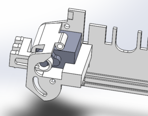
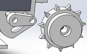
Thus, the a different tension system based off of Jeff Gomes‘ own Goliath model was created; it was a swivel-based tension system that would loosen as it was pulled into the model and tightened as it was pushed outwards. This allowed the tension of the tracks to be changed appropriately while keeping the blade to be flush with the floor.
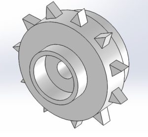
In order to have gotten the idler wheels to not be grinding against the screw that holds down the swing arm, one side of the model had to be reduced in shape significantly. The drive motor wheels were also designed to no longer have D-shaped holes. Instead, the holes were circular with a hole leading from the outer surface of the wheel to the shaft hole. This allows easier 3D printing while keeping the wheel in line with the shaft by tightening a small screw to the flat side of the shaft.
Top Panel
E-racer had intended to be compatible with the ArxTerra Control Panel by using a pilot’s phone’s front or back-facing camera. The camera would be placed on top of the robot, and a small periscope would be used for proper visual feedback to the control panel. Strangely, the team found that the design of E-Racer seemingly did not properly account for this, as the attachment meant to increase the phone above the tread’s maximum reach was too small for larger phones and unreliable when in motion.
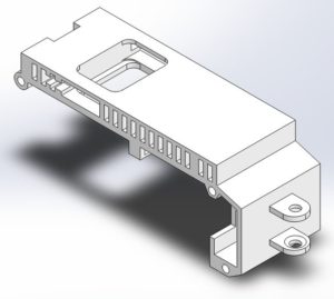
The final design of MicroDozer seeked to improve on this design by changing the height increase from an attachment to simply increasing the height of the top panel itself. Although this did help with securing the phone on top of the robot, it would require a significant increase in printing material. To combat this increase of cost, through holes were made along the length of the robot’s expanded top. Along with the length-wise holes, a larger, top-down hole was added to the design to allow wires to reach from inside the chassis to any external components that could be added to the design.
The final addition to the top was the inclusion of a port for attaching the modular lint roller. This was inspired by Spring 2019’s Gradbot initial bearing wheel design from their preliminary design review, found here. The port was simply made larger than the intended bearing ball, thin enough to allow the parts to click together, and thick enough to not break when docking the bearing.
Lint Roller Attachment
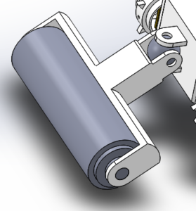
Figure 11: Lint roller (grey) in its holder (white), attached to the top panel port of MicroDozer V3 using a bearing ball.
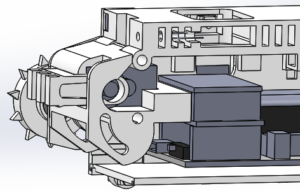
In order to increase the utility of µDozer as an in-home clean-up robot, a lint roller was added to the design after the critical design review. Fortunately, since there were no electronics associated with the lint roller, the design went smoothly and quickly. Measurements of the expected lint roller were made and applied to the roller chassis design. A bearing ball was used to clip the roller to the main chassis. This allowed the lint roller to move around without limiting the movement of the robot too much, as it could lift and lower over obstacles it could not pick up, as well as swivel side-to-side as the robot turned.
2. Accounting for the Custom Shield and Removable Components
LED and Photoresistor (LDR)
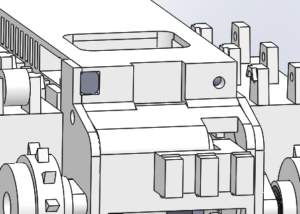
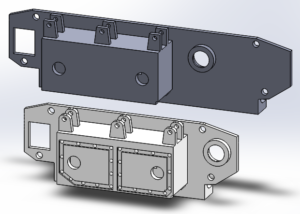
Figure 12: Front view of the housing for the LDR (left grey) and LED (right grey) in the top panel of MicroDozer V3.
After the team had agreed to what components to add to the custom shield for the robot, thought had to go into designing where the components would be housed. It was difficult to incorporate all of the non-ultrasonic components because they relied heavily on forward visibility. This was difficult to incorporate because the bulldozer blade was in the front of the robot.
To reduce and hopefully eliminate the interference from the blade, its height off of the ground was decreased. After this decrease, the LED and LDR could be housed within the top of the robot. Housing holes were left in the front-facing portion of the model so that they would be able to both read and emit light without interference from the blade. Their wiring would be fed into the primary hole of the top and into the 3DoT shield.
Note: When using component-specific dimensions for a model to hold objects in place, make sure to account for different LED, LDR, and other component sizes.
Ultrasonic Sensors
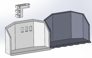
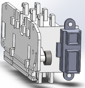
Conceptually, the ultrasonic sensors were the easier problem to solve, as they could simply be housed within the side panels. Actually incorporating this idea was more difficult than expected. To be able to modulate the ultrasonic sensors, the rectangular blocks of the side panels became wholly detachable for easier insertion. In order to make the blocks detachable and prevent the amount of screws required for assembly, the panels and blocks would have male and female connections. To allow the connections to be made without interfering with the ultrasonic pins, the middle top of the panel was eliminated. One change kept leading to another.
Infrared (IR) Sensor
Initially, it was believed that the IR could simply be added to the top of the robot, similar to the design of the LED flashlight and LDR detection system; however, the size of the IR sensor was grossly underestimated, and the idea had to be reworked entirely. Fortunately, the IR sensors had a narrow detection angle at only around 15°. The IR platform was then designed to hold the sensor off to the side of the robot while remaining forward-facing, avoiding the blade.
After placing the IR sensor on the bot, the wiring had to be considered. Running the wires through the top of the robot, as was initially considered, would leave the wires to vulnerable. Thus, another through hole was put into the side panel that held the IR sensor such that the wires could be fed straight into the robot and the 3DoT.
PCB Stacking
In the last project status meeting, the option for PCB stacking was requested to allow the inclusion of an optional inertial measurement unit (IMU). The last projected day to submit the model files for 3D printing was only three days after this request, so the only solution available with that amount of time was to, once again, expand the chassis. However, not only was the chassis increased length-wise, it was also increased height-wise. Thankfully, the dimensions were increased by no more than 20mm in either direction; this allowed us to remain within the expected size constraints.
Conclusion
Designing the models for Goliath had been a very time-consuming but rewarding task. There were many creative ideas brought to the table for overcoming design choices that had been made for the sake of challenge, such as the process of changing the model to accommodate an entire custom shield system with only a few weeks of the semester remaining. Hindsight is 20/20, and there are many improvements that can be made to the current model of MicroDozer. If there is one thing one must keep in mind while modeling such a small project, it is to remember these core ideas:
- Accommodate for margin of error. If something looks just right in a modeling program, it is probably too tight of a fit.
- Coordinate with the entire team so that the model can adapt quickly to new requirements.
- Be open to ideas and practice creativity. One solution might be a hindrance for another part of the model.
- Consider. Wires. Make them as short as possible, or else the model might be too small to handle them. A visual cable tree will do no good at that point.

