MicroFOBO
Author/s: Michelle Mitich, James Spane, and Paco Ellaga
Table of Contents
Executive Summary
MicroFOBO is a scaled-down in size and modernized version of the 1980s robot. Gone are the days of robots with conveyor belt-like walking mechanisms – this robot utilizes two legs to walk forward and turn to the left and right! Additional features include remote control capability via the ArxRobot app and an ultrasonic sensor for automatic object detection and avoidance.
Program and Project Objectives
MicroFOBO is a biped servo robot with six degrees of freedom and has several goals. The first of the goals is to get MicroFOBO walking on a flat surface. Additionally, MicroFOBO should be improved upon over its second generation by stabilizing movement via refined power management, implementing a micro-servo with an increased stall-torque rating, and mechanically augmenting the hips and legs (and possibly the head and feet). MicroFOBO will also have a feature that allows it to auto-detect objects and avoid them
Mission Profile
MicroFOBO will walk two laps around the perimeter of a three foot square pathway in three minutes or less. During the first lap only right turns will be made and during the second lap only left turns will be made. MicroFOBO’s walking actions will be controlled remotely via Bluetooth technology and the ArxRobot app. MicroFOBO will have an ultrasonic sensor, allowing it to walk up to an object, detect it, and turn away from it.
Project Features
MicroFOBO utilizes larger 19g micro servos with 55% higher stall torque rating than the previous generation (2.8 kg/cm @ 4.8V versus 1.8 kg/cm @ 4.8V). Redesigns of the legs and hips were implemented to accommodate the slightly larger servos and increase the mechanical stability of the robot by lowering its center of mass. MicroFOBO also features Bluetooth remote control via the ArxRobot mobile app, a custom servo shield that uses a shift register for servo control, and an ultrasonic sensor for object detection and avoidance.
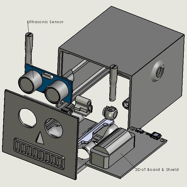
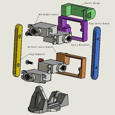
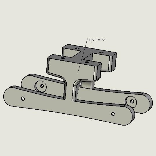
The main features and redesign components are called out in the 3D model explosions below.
The MicroFOBO head design was created by Jeff Gomez. The design remained untouched and a custom pcb shield was added to the 3DoT board to control the servos.
A slightly larger 19g micro servo was selected. As a result, the leg needed to be widened and lengthened to accommodate the servo’s larger size.
The selection of larger servos required the hips to be widened and deepened. Widening the hips came with the added benefit of increased mechanical stability. Additionally, the hips were consolidated from a three part assembly into one.
Requirements
Engineering Standards and Constraints
Applicable Engineering Standards
- Bluetooth Special Interest Group (SIG) Standard (supersedes IEEE 802.15.1)
- C++ standard (ISO/IEC 14882:1998)
- Federal Communications Commission (FCC) Relevant standards for a product implementing a 2.4GHz radio, FCC Intentional Radiators (Radio) Part 15C, and Unintentional Radiators FCC Part 15B for CPU, memories etc.
- NXP Semiconductor, UM10204, I2C-bus specification and user manual.
- ATmega16U4/ATmega32U4, 8-bit Microcontroller with 16/32K bytes of ISP Flash and USB Controller datasheet section datasheet, Section 18, USART.
- USB 2.0 Specification released on April 27, 2000, usb_20_20180904.zip
- Motorola’s SPI Block Guide V03.06
Environmental, Health, and Safety (EH&S) Standards
- CSULB Environmental Health & Safety (EH&S)
- IEEE National Electrical Safety Code (NESC)
- NCEES Fundamental Handbook (FE) Reference Handbook
- Electronic Waste Handling and Disposal Procedures
Project Unique Constraints
L1.8 – MicroFOBO shall incorporate the 3DoT v8 or later series of boards.
L1.6 – MicroFOBO shall contain one or more custom-designed 3DoT shields.
L1.11 – MicroFOBO shall be written in the Arduino De facto Standard.
L1.12 – MicroFOBO shall be in compliance with the 3DoT Command Telemetry Packet specification.
L1.5 – MicroFOBO shall be controlled via Bluetooth 4.0 in compliance with the Bluetooth Special Interest Group (SIG) Standard.
L1.13 – MicroFOBO shall be completed by Tuesday December 17, 2019.
L1.10 – MicroFOBO will be constrained to a cost not to exceed $500.
Project Level 1 Functional Requirements
L1.1 – MicroFOBO shall stand on its own without outside assistance.
L1.2 – MicroFOBO shall complete an automated walking test where it turns right to avoid an object.
L1.3 – MicroFOBO shall complete an automated walking test where it turns left to avoid an object.
L1.4 – MicroFOBO shall use an ultrasonic sensor for object avoidance.
L1.6 – MicroFOBO shall include a custom shield which interfaces eight (8) servos and the ultrasonic sensor with the 3DoT board.
L1.7 – MicroFOBO’s head shall allow external access to all necessary components on the 3DoT board without removal.
L1.9 – MicroFOBO should have a minimum power capability of 1500 mAh.
System/Subsystem/Specifications Level 2 Requirements
L2.2.1 – For the first section of the square, MicroFOBO shall walk at least 1.5 ft (+/- 10%) forward without deviating more than 30° from original position.
L2.2.2 – During the first walk sequence, upon detection of an object MicroFOBO shall turn right until the object is no longer detected in front of it by the ultrasonic sensor.
L2.2.3 – For the second section of the square, MicroFOBO shall walk at least 1.5 ft (+/- 10%) forward without deviating more than 30° from original position.
L2.2.4 – During the second walk sequence, upon detection of an object MicroFOBO shall turn right until the object is no longer detect in front of it by the ultrasonic sensor.
L2.2.5 – MicroFOBO shall use eight micro servos with a minimum stall torque of >1.8 kg/cm @ 4.8V
L2.3.1 – For the first section of the square, MicroFOBO shall walk at least 1.5 ft (+/- 10%) forward without deviating more than 30° from original position.
L2.3.2 – During the first walk sequence, upon detection of an object MicroFOBO shall turn left until the object is no longer detected in front of it by the ultrasonic sensor.
L2.3.3 – For the second section of the square, MicroFOBO shall walk at least 1.5 ft (+/- 10%) forward without deviating more than 30° from original position.
L2.3.4 – During the second walk sequence, upon detection of an object MicroFOBO shall turn left until the object is no longer detect in front of it by the ultrasonic sensor.
L2.3.5 – MicroFOBO shall use eight micro servos with a minimum stall torque of >1.8 kg/cm @ 4.8V
L2.4.1 – During a walk sequence, if an object is detected MicroFOBO shall initiate a turn sequence.
L2.4.2 – MicroFOBO shall exit an automated turning sequence when an object is no longer detected by the ultrasonic sensor.
L2.5.1 – The app’s user interface shall have a directional control pad for predetermined movements.
L2.5.2 – MicroFOBO shall be able to move its legs in a walking motion when the walk forward command is given from the ArxRobot app.
L2.5.3 – MicroFOBO shall be able to start a turn sequence manually in the left or right direction using the ArxRobot app.
L2.5.4 – MicroFOBO will use an HM-11 Bluetooth module connected to the 3DoT to establish the connection.
L2.5.5 – Using Telemetry controls, MicroFOBO should be able to walk forward one foot without outside assistance.
L2.5.6 – Using Telemetry controls, MicroFOBO should be able to turn left without outside assistance.
L2.5.7 – Using Telemetry controls, MicroFOBO should be able to turn right without outside assistance.
L2.6.1 – The custom shield shall have SMD components, including the CD4017 decade counter.
L2.6.2 – The custom PCB will be fully designed in Eagle CAD.
L2.6.3 – The custom shield will implement a shift register (CD4017) to control all eight (8) servos.
L2.6.4 – All of the components on the PCB shall be soldered by hand.
L2.7.1 – MicroFOBO shall be 3D printed using Onyx material.
L2.7.2 – MicroFOBO shall be designed using Solidworks.
L2.7.3 – MicroFOBO shall have two legs and two feet.
L2.7.4 – MicroFOBO’s center of mass will be lower than that of previosu generations.
L2.7.5 – MicroFOBO’s head will house the 3DoT board, custom PCB, ultrasonic sensor, and external battery.
L2.7.6 – MicroFOBO’sh ead shall allow access to turn on and off the 3DoT board without removal.
L2.7.7 – The three-part hip assembly shall be converted into a single part.
L2.8.1 – The ArxRobot app will be translated into C++ from Project Biped’s FOBO Poser app (which was written in C#).
Allocated Requirements / System Resource Reports
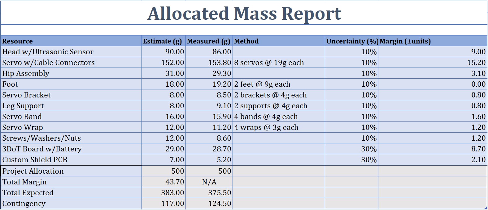
The measured mass came in under the estimated mass for two primary reasons. For the estimated mass, a standard kitchen scale with less resolution and accuracy was used when weighing an older generation of MicroFOBO. Meanwhile, for the measured mass of the Fall 2019 MicroFOBO, a laboratory scale which had higher resolution and accuracy was used. Furthermore, only the head of MicroFOBO was printed in onyx material (which is heavier than other print materials available) due to the need for several reprints of the hip joint, legs, and feet and production time constraints at the Innovation Space in CSULB’s library.
The total expected power allocation according to our report is 1270 mA. This is based on each servo drawing 150 mA with a 30% margin, considering the servos will all be under different loads at all moments in Micro-FOBO’s walking sequence. Our 3DoT will run off the on board battery along with the ultra sonic sensor and the HM-11 Bluetooth module. The eight servos motors will run off an external battery pack. Our external battery pack consists of two of the CR123 batteries in series. This will increase their overall mAh capacity, but their instantaneous current will be about the same as the original battery once fully loaded. The major benefit being the battery is dedicated to the exclusively to the servos. One thing to be cautious of that our power allocation report doesn’t account for is the possibility of stalling out a servo motor, which can have a current draw of 600mA or more and can cause our whole system to fail.
Project Report
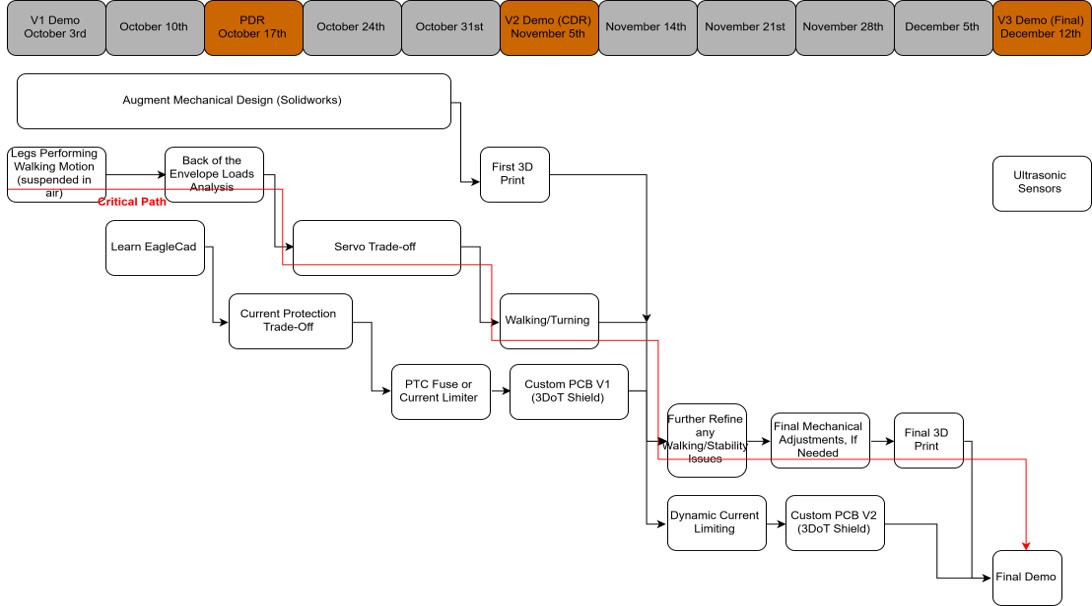
The following section reviews the project’s Work Breakdown Structure (WBS), Product Breakdown Structure (PBS), cost/budget, and schedule.
Project WBS and PBS
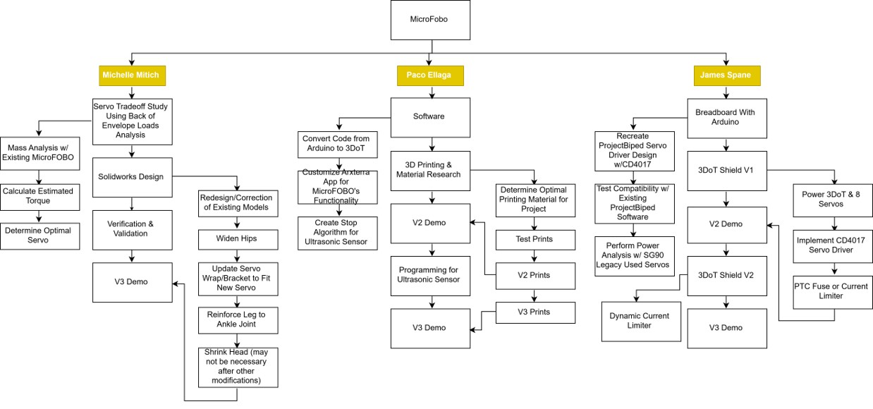
The WBS defines the required tasks for successfully completing MicroFOBO and the individual responsible for completing them.
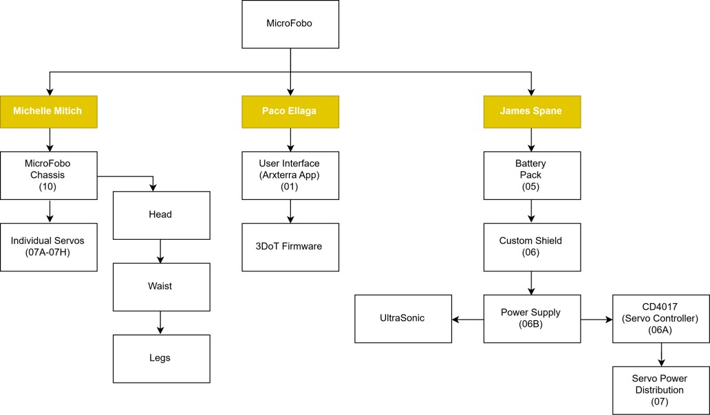
The PBS defines the major subsystems within MicroFOBO and the individual responsible for completing them.
Cost
The total cost of Micro-FOBO was $450.71. The majority of the cost was from the two 3DoT purchases that were necessary for rapid prototyping and testing, which came out to $172.30. These were a required purchase due to the requirements of the project. The next highest cost was the 8 HS-82MG micro servos which came out to $164.00. We burned out at least 10 SG-90 micro servos we already previously owned as we were testing and determined with a load and torque analysis that stronger and more stable servos were necessary for this project. They also needed to remain micro servos in order to fit the form factor of Micro-FOBO. The combination resulted in more expensive than usual servos. Overall the custom PCB was very affordable as it only required one print and minimal parts. The most expensive part of that process was the Solder paste, and that was due to being bought locally rather than online. Overall our project remained under the $500 budget set. This is largely due to being able to source a large amount of parts from past projects, which is why we converted to a self-funded project.
Schedule
Concept and Preliminary Design
MicroFOBO was originally designed by the Spring 2018 project team to be a miniaturized version of a robot called FOBO which was created by Jonathan Dowdell at Project Biped. The Spring 2018 team was successful in scaling the robot down to approximately 60% of FOBO’s original design, however, they were unable to successfully get the robot to walk. The Spring 2018 team’s design was our jumping off point for tackling our goal of making this biped robot walk.
Literature Review
The most significant literature reviewed for our project was that of prior 400D MicroFOBO projects (Spring 2018), the Project Biped website, the Division/Training Resource Documents located on Arxterra, and YouTube Solidworks tutorials.
Project Biped’s website had most of the code already written to get FOBO walking, it primarily needed to be translated into C++. This will be discussed further in detail in the firmware section of this blog post.
Since no one in our group had ever used Solidworks, it was the primary job of the individual taking on the mechanical engineering role to get up to speed on how to use this 3D modeling software. Enough cannot be said about the amazing resource that Richard Haberkern was over at the Invention Therapy channel on YouTube. Without Invention Therapy’s series of short tutorials, learning Solidworks would have been a much more painful process.
Design Innovation
MicroFOBO Fall 2018 implemented the following new design innovations:
- A shift register (CD4017) for servo control instead of the decoder (HCF4017BE) and I2C switch (TCA9548A) used in previous generations
- 19g micro servos with metal gears, not plastic) rated with a stall torque of 2.8 kg/cm @ 4.8V instead of the common 9g SG90 micro servos rated with a stall torque of 1.8 kb/cm
- Converted hip joint assembly from three parts down to one
- Widened the hip joint and legs to lower the center of mass and increase mechanical stability
System Design / Final Design and Results
System Block Diagram
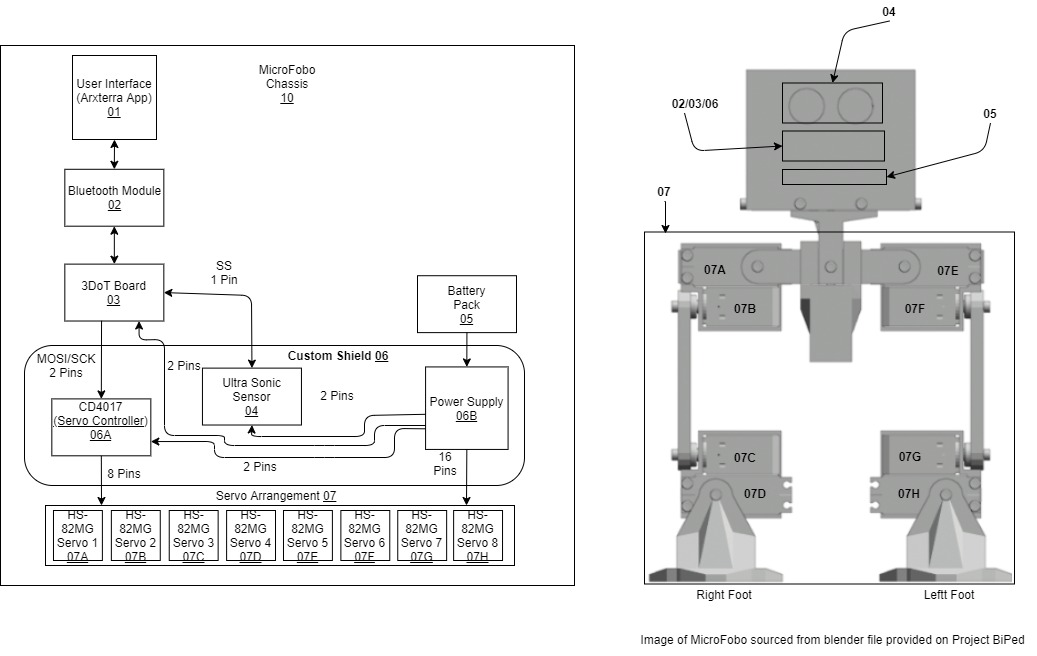
Our system is designed to take an input from the user using the ArxRobot App (01), from there it will use Bluetooth to communicate with the Bluetooth module (02) on the 3DoT Board (03) to direct the control the movements of Micro-FOBO. Micro-FOBO will use a custom shield (06) which will take an input from the 3DoT’s MOSI and SCK pins and output them to the CD4017 decade counter (06A) which will act as our servo driver. The CD4017 (06A) will output to the signal pins on each of the servos (07). Also contained on the custom shield (06), is the ultra-sonic sensor (04) which will receive an output from the MISO pin of the 3DoT (03). Lastly the custom shield will contain a connection for the external power supply (06B) which will most likely consist of a buck converter than connects with the battery pack (05).
Interface Definition
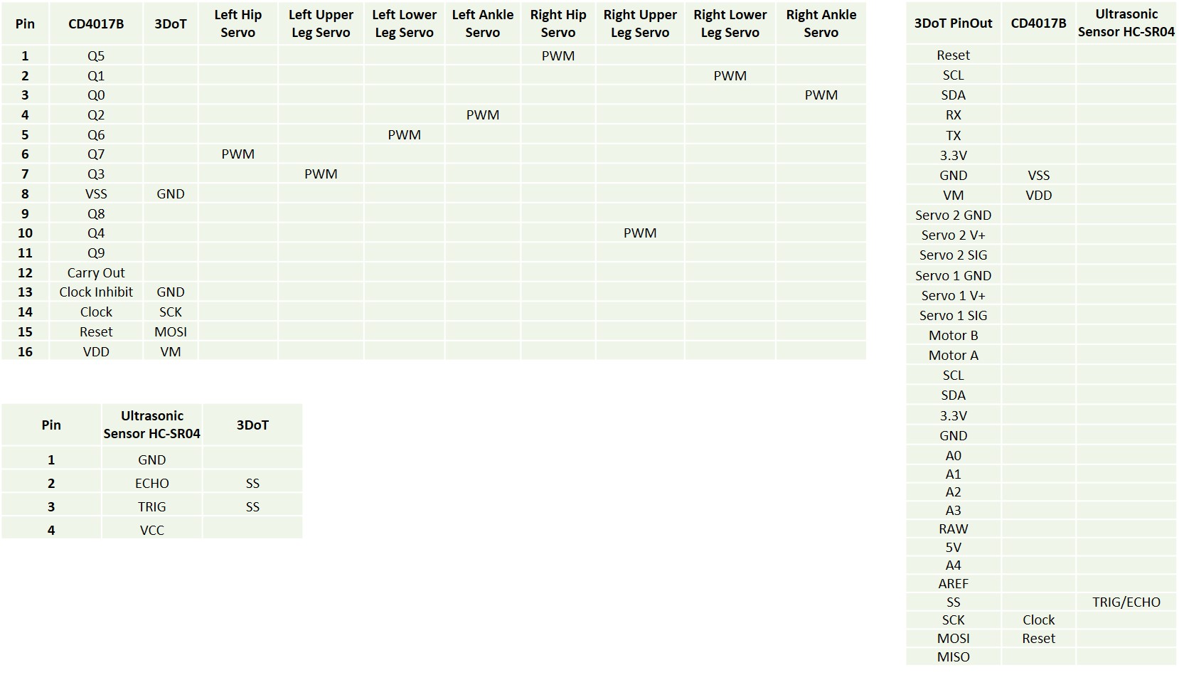
The interface matrix shows the pin assignments for the 3DoT board, shield (shift register), and ultrasonic sensor.
With respect to the interface control, a result of Gen 3, MicroFobo has become a project where the user will now encounter 2 types of interface systems. One being the Fobo Poser App developed by Jonathan Dowdall of Project Biped (C) 2012 and of the ArxRobot App developed by Arxterra modified by Gen 3 Team MicroFobo. They work in conjunction with the firmware code developed our team as to join the 2 apps together. With Fobo Poser, the user will need a computer, and for the ArxRobot App, it is downloadable (as by permission of Arxterra) via smart device and laptop through the ArxRobot Control Panel.
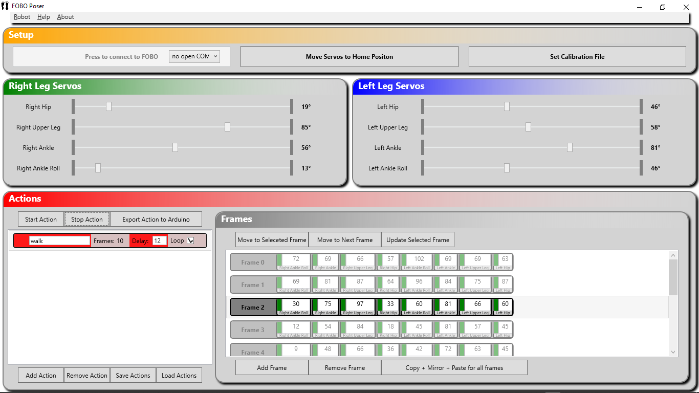
The design Fobo Poser acts as the user’s way to start up their journey with calibrating and operating MicroFobo. The user will need to download the app and the remote_control.ino file from Project Biped as a way to calbrate any newly built MicroFobo. A seasoned maker or hobbyist may not need the Fobo Poser’s App calibration method’s, due to instinctively knowing where centerpoints are when installing the servo’s, but they will need for the special Action class file that is read ultimately as through Arduino IDE. For calibration, please study the image below.
From here the multiple sliders will help calibrate your MicroFobo in standing order. Once aligned, the user will export their Action to Arduino and use that ino file to run off the 3DoT. But, due to the process of development, please refer to our firmware section how that file fully reforms into a working .ino that will allow compatibility to ArxRobot.
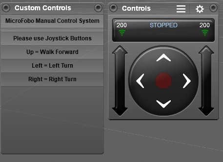
As for the app, the result allowed for a new feature that MicroFobo has never had from previous generations at Arxterra: full manual control of MicroFobo custom movements via Bluetooth command and the through the ArxRobot app. This method is also completely modular where the user can import and customize their own Action matrices and execute them via Joystick command. As shown below this is the final result. Improvements are for sure possible as MicroFobo can use ultrasonic sensors in the Navigation.ino from Project Biped and was also proved via verification using the 3DoT V9 board.
References:
Modeling/Experimental Results
MicroFOBO was modeled in Solidworks. Adjustments were made to the hip joint and legs in an attempt to incorporate the new, larger servos into the design as well as stabilize the mechanical integrity of the robot to increase our chances of getting him to walk. One of the biggest concerns from a mechanical perspective was the lofty mass of the head and the internal components housed within versus the rest of MicroFOBO’s body.
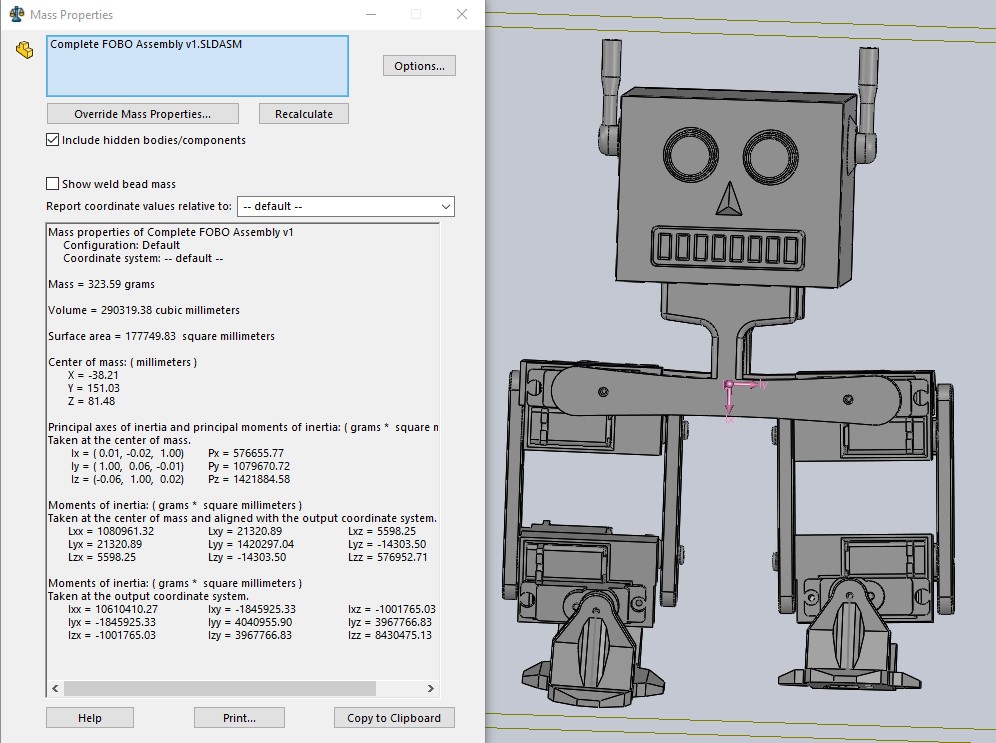
Generation 1 of MicroFOBO had a high center of mass due to the weight of its head, and the focus of the additional modeling study was to determine whether the mechanical changes made to incorporate the newer servos would be sufficient to lower the center of mass.
MicroFOBO was assembled in three stages: the head assembly, the hip joint, and the leg assemblies and feet. Once positioned into Solidworks, a center of mass evaluation was performed. When comparing our robot’s center of mass to the center of mass of MicroFOBO Generation 1, we found that our body with its redesigned hip joint and legs had a lower center of mass.
Mission Command and Control
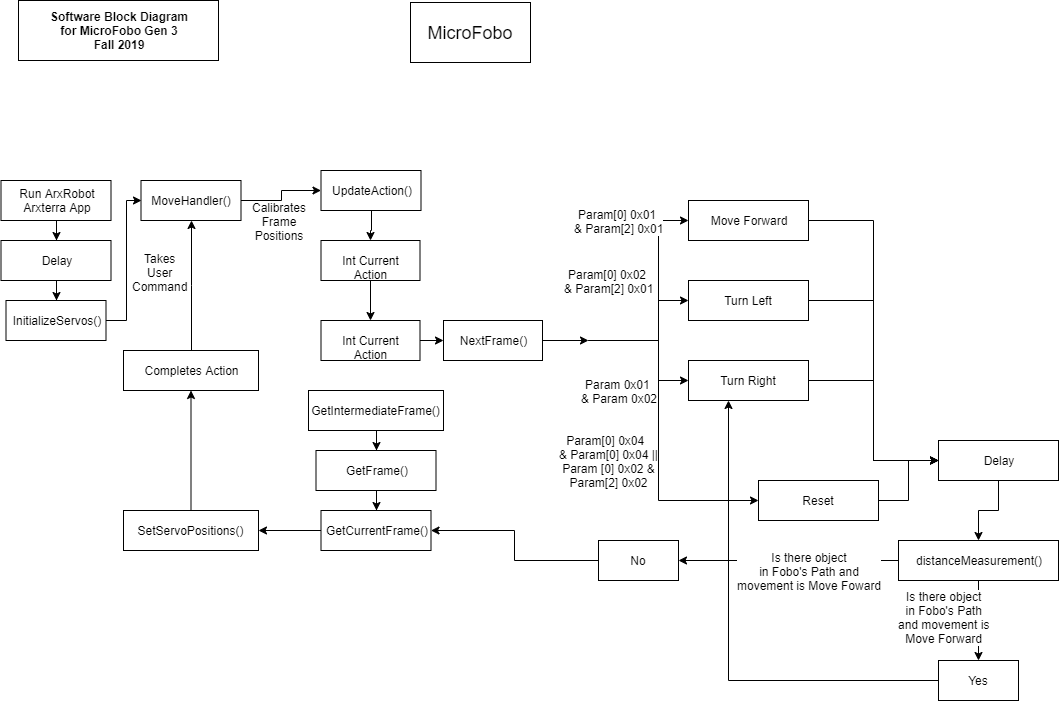
For Gen 3 MicroFobo, our system completed with two models. One that provided a proof of concept to integrate the 3DoT with Ultrasonic Sensors wall detection and the other with the bluetooth user command system. The model provided shows all of the component as a full completion as if were fully completed.
In reality, the Navigtion.ino provided by Project Biped (link: http://www.projectbiped.com/prototypes/fobo/navigation) controls the ultrasonic, but had no bluetooth. So, to modify the model, It would instead start at InitializeServos(), MoveHandler() would only be UpdateAction(), and the MoveFoward() and TurnRight() would be active in movement options. For the Gen 3 modified code to work with Arxterra’s ArxRobot Application, only the distanceMeasurement and loop to TurnRight() would be removed. This process was achieved by having both these sets of codes on two different 3DoT boards.
Overall, by breaking down the structure, if the Navigation.ino is used, once the user turns on MicroFobo, it will start walking and continuously keep walking until it sees and wall and will loop back to turn right. If walking forward or if it is already set to be turning right, it will run through the selected matrix and move and update all servo positions constantly.
Now, if the new custom code for the bluetooth is running, Fobo will turn on when powered, but will be inoperable until connected to the ArxRobot App and set up it’s servos. From there the MoveHandler() on the Joystick commands will control MicroFobo’s actions by either walking forward, left or right. By pressing the center button or down, the servos will reset to a 60° home position. The ultrasonic sensor will be ignored and only be controlling walking or turning gait uninterrupted. If the user lets go, or resets control, MicroFobo will return to the 60° home position of the servos and await the next command.
Electronic Design
PCB Design
The progression of the PCB design from Fritzing diagram, to physical breadboard, to PCB schematic, to PCB layout is discussed in the related blog post here.
Firmware
Mechanical/Hardware Design
MicroFOBO has an extensive mechanical design which is covered in a blog post here.
Verification & Validation Test Plan
Final Testing Day
Mission Profile: Micro-FOBO shall make two laps of a 1 ½’ Square track, the first lap will be clockwise the second counterclockwise. Walking on a flat terrain (ECS-315). Micro-FOBO will be controlled remotely through Bluetooth technology and the ArxRobot app for two of the corners. Micro-FOBO will autonomously turn if it encounters a wall at two of the corners.
| Updated Requirements List | |||
| L1 | 1 | Microfobo shall stand on it’s own without outside assistance | |
| Walk Forward and Right Requirements | |||
| L1 | 2 | Microfobo Shall complete an automated walking test where it turns right to avoid an object | |
| L2 | 2 | 1 | For the first section of the square Micro-FOBO shall walk at least 1.5ft (+/- 10%) forward within 30 degrees of original orientation |
| L2 | 2 | 2 | During the first walk sequence, upon detection of an object Microfobo shall turn right until the object is no longer detected in front of it by the ultra sonic |
| L2 | 2 | 3 | For the second section of the square Micro-FOBO shall walk at least 1.5ft (+/- 10%) forward within 30 degrees of original orientation |
| L2 | 2 | 4 | During the second walk sequence, upon detection of an object Microfobo shall turn right until the object is no longer detected in front of it by the ultra sonic |
| Walk Forward and Left Requirements | |||
| L1 | 3 | Microfobo shall complete an automated walking test where it turns left to avoid an object | |
| L2 | 3 | 1 | For the first section of the square Micro-FOBO shall walk at least 1.5ft (+/- 10%) forward within 30 degrees of original orientation |
| L2 | 3 | 2 | During the first walk sequence, upon detection of an object Microfobo shall turn left until the object is no longer detected in front of it by the ultra sonic |
| L2 | 3 | 3 | For the second section of the square Micro-FOBO shall walk at least 1.5ft (+/- 10%) forward within 30 degrees of original orientation |
| L2 | 3 | 4 | During the second walk sequence, upon detection of an object Microfobo shall turn right until the object is no longer detected in front of it by the ultra sonic |
| L2 | 2,3 | 1 | Microfobo shall use eight micro servos with a minimum stall torque of > 1.8kg/cm @ 4.8V |
| Ultra Sonic Requirements | |||
| L1 | 4 | Microfobo shall use an ultra sonic sensor for object avoidance | |
| L2 | 4 | 1 | During a walk forward sequence, if an object is detected Micro-FOBO shall initiate a turn sequence |
| L2 | 4 | 2 | Microfobo shall exit an automated turning sequence when an object is no longer detected by the ultra sonic |
| Bluetooth / Telemetry Controls Requirements | |||
| L1 | 5 | Microfobo shall be be controlled via Bluetooth 4.0 in compliance with the Bluetooth Special Interest Group (SIG) Standard (supersedes IEEE 802.15.1). | |
| L2 | 5 | 1 | The App’s user interface shall have a directional control pad for predetermined movements |
| L2 | 5 | 2 | Microfobo shall be able to move its legs in a walking motion when the walk forward command is given from the Arxterra App |
| L2 | 5 | 3 | Microfobo shall be able to start a turn sequence manually in the left or right direction using the Arxterra App |
| L2 | 5 | 4 | Microfobo will use an HM-11 bluetooth module connected to the 3DoT to establish the connection |
| L2 | 5 | 5 | Using Telemetry controls Microfobo should be able to walk forward 1 ft. without outside assistance |
| L2 | 5 | 6 | Using Telemetry controls Microfobo should be able to turn left without outside assistance |
| L2 | 5 | 7 | Using Telemetry controls Microfobo should be able to turn right without outside assistance |
| Custom Shield Requirements | |||
| L1 | 6 | Micrfobo’s design shall include a custom shield to interface the eight (8) servos and the ultra sonic sensor with the 3DoT Board | |
| L2 | 6 | 1 | The custom shield shall have SMD components, including the CD4017 Decade Counter |
| L2 | 6 | 2 | The custom PCB will be full designed in Eagle CAD |
| L2 | 6 | 3 | The custom shield will impliment a shift register (CD4017) to control all eight (8) servos |
| L2 | 6 | 4 | All of the components on the PCB shall be saudered by hand |
| 3D Modeling Requirements | |||
| L1 | 7 | Microfobo’s head shall allow external access to all necessary components on the 3DoT board without removal | |
| L2 | 7 | 1 | Microfobo shall be 3D printed using Onyx material |
| L2 | 7 | 2 | Microfobo shall be designed using Solidworks |
| L2 | 7 | 3 | Microfobo will have two legs and two feet |
| L2 | 7 | 4 | Microfobo’s center of mass will be lower than that of previous generations |
| L2 | 7 | 5 | MicroFobo’s head will contain the 3DoT, Custom PCB, Ultrasonic Sensor, and external battery |
| L2 | 7 | 6 | Microfobo’s head shall allow access to turn on and off the 3DoT board without removal |
| Programming Requirements | |||
| L1 | 8 | Microfobo shall utilize the 3DoT board | |
| L2 | 8 | 1 | The ArxRobot app will be translated into C++ from Project Biped’s FOBO Poser app (which was written in C#). |
| L2 | 8 | 2 | The three-part hip assembly shall be converted into a single part |
| L1 | 10 | Microfobo’s expenditures will not exceed $500 | |
| L1 | 11 | Microfobo should have a minimum power capability of 1500 mAh |
| Matrix/Plan | Matrix/Plan | Matrix/Plan | Matrix/Plan | Plan |
| Test Case | Test Procedure | Requirement(s) Tested | Data to Be Collected | Pass Criteria |
| T1 | MicroFOBO will be fully assembled, including the 3DoT, UltraSonic, the external battery, and all of the servos Motors, and then placed on a table to stand on its own. | L1-1, L1-7, L2-7-3,L2-7-5,L2-7-6 L1-4, L2-4-1,L2-4-2 | 1. Visually identify if MicroFOBO is standing unassisted. 2. Confirm all components are within the head. 3. Visually confirm MicroFOBO has two legs and two feet. 4. Visually confirm Microfobo head allows access to the 3DoT usb port and the 3DoT power switch. |
1. Fobo has not fallen over after a period of time. 2. If no components, besides the servos and ultaasonic sensors are exposed. 3. If there are clearly two legs and two feet. 4. If user can manually turn 3Dot On/Off and/or plug/unplug usb. |
| T2 | A autonomous navigation file will be uploaded to MicroFOBO with the response to the right turn preset. First with microFOBO suspended, we will test if he automatically initiates the walk forward sequence, then we will test if the Ultra sonic connector responds to an object in front of it. Once this is completed we will set microfobo to start walking forward, then once it reaches approximately 1.5ft we will place an object in front of it so it turns right. Once it turns right we will confirm it walks another 1.5ft forward and place another object in front of it. It should then turn again. | L1-2; L2-2-1 through L2-2-4; L2-2,3-4; L1-4; L2-4-1; L2-4-2; L1-6 | 1.Confirm MicroFOBO initiates the walk forward sequence 2. Confirm the ultrasonic responds to an object in front of it and initiates a turn sequence until the object is removed 3. Confirm Microfobo walks forward 1.5ft for the first section of the walk 4. Confirm MicroFOBO turns right when the object is placed in front of it 5. Confirm Microfobo continues to move forward when the object is no longer in front of it another 1.5ft 6. Confirm Microfobo Initiates the turn sequence |
When MicroFobo is connected to neccessary power sources, the robot can.. 1. Automatically walk forward 2. Automatically turn right upon seeing an obstacle 3. Successfully completes each walk and turn sequence weighted |
| T3 | A autonomous navigation file will be uploaded to MicroFOBO with the response to the left turn preset. First with microFOBO suspended, we will test if he automatically initiates the walk forward sequence, then we will test if the Ultra sonic connector responds to an object in front of it. Once this is completed we will set microfobo to start walking forward, then once it reaches approximately 1.5ft we will place an object in front of it so it turns left. Once it turns left we will confirm it walks another 1.5ft forward and place another object in front of it. It should then turn again. | L1-3, L2-3-1 through L2-3-4 L2-2,3-4; L1-4; L2-4-1; L2-4-2; L1-6 | 1.Confirm MicroFOBO initiates the walk forward sequence 2. Confirm the ultrasonic responds to an object in front of it and initiates a turn sequence until the object is removed 3. Confirm Microfobo walks forward 1.5ft for the first section of the walk 4. Confirm MicroFOBO turns left when the object is placed in front of it 5. Confirm Microfobo continues to move forward when the object is no longer in front of it another 1.5ft 6. Confirm Microfobo Initiates the turn sequence |
When MicroFobo is connected to neccessary power sources, the robot can.. 1. Automatically walk forward 2. Automatically turn left upon seeing an obstacle 3. Successfully completes each walk and turn sequence weighted |
| T4 | MicroFobo will also then be connected to a different 3DOT board that has code that allows for the user to control the robot’s movement patterns manually via blutooth over the Arxterra ArxRobot app. | L1-5 and L2-5-2 through L2-5-7 | 1. Test the capability of Blutooth connections. 2. Manual control of moving robot foward , turning left, and turning right. 3. Success of Poser App matrices being read in the the translated code for ArxRobot App |
1. HM11 blutooth module works and connect 3DoT and phone app, ArxRobot. 2. The directional move command responds with MicroFobo moving in accordance to user input 3. |
| T5 | The Arxterra App will be customized catering to MicroFobo and allow the user ease of access to fully control the robot. | L2-5-2 | 1. The existance of a user interface on the ArxRobot App. 2. Test is commands and telemetry are indeed being sent back and forth. |
1. App can be opened and used during the test. 2. If Trace is left on and when commands are being sent, the response is being recorded with a visual response happening on the robot. |
| T6 | By opening Solidworks, all files present show that a majority is redesigned to prove various imporvements of MicroFobo. | L1-7 and L2-7-1 through L2-7-6 | 1. Verification that the program used is indeed Solidworks. 2. Verification of center of mass being lowered. 3. MicroFobo having two legs and two feet. 4. Verifies the hip was redesigned to a single T-shaped piece versus 3 separate pieces |
1. If Solidworks with MicroFobo files are opened with clearly work completed on it. 2. Can be physically found/calculated in Solidworks. 3. The model contains the modification for the legs. 4. The hip model is loaded and completed. |
| T7 | By opening Eagle, all files present show the development of the PCB and all SMD components that are encase inside and on MicrFobo. Compare it to the existing PCB board used with MicroFOBO. As well as present an unsoldered PCB to show it was hand soldered | L1-6, L2-6-2,L2-6-3.L2-6-4 | 1. Verification of the PCB being designed and printed from Eagle CAD software. 2. PCB contains the CD4017 decade counter, 8 servo connections, and ultrasonic sensor. |
1. Can open the PCB on Eagle and passed verification. 2. All components can be found or are labelled within the diagram. |
| T8 | By looking at previous receipts, prove that MicroFobo was redesigned in and 3D printed using Onyx Carbon FIber | L1-7 and L2-7-1 through L2-7-6 | 1. Prove that MicroFobo is printed in Onyx (carbon fiber) 3D printing filament. | 1. Can pull out the receipt and/or do a viasual inspection of the 3D printed material of the robot. |
| T8 | MicroFobo will be placed on a table with the proper tools and the team will given the allotted time to complete a full disassemble and reassemble of the robot | L1,L2-9-1,L2-9-2 | 1. Full assembly/disassembly are tested to be complete within 20 minutes 2. Will show the use of the custom built PCB shield for the 3DoT 3. Will show the custom PCB will have complete component integration of 8 servos connections, Ultrasonic Sensor, and a SMD CD4017 decade counter 4. Will prove that MicroFObo has two legs and two feet |
1. Full disassemble/assembly is completed in 20 minutes |
Concluding Thoughts and Future Work
While the mechanical design on this robot was solid enough to allow FOBO to walk and bend over without falling over, there are improvements that could be made and simulations that would prove the design before printing. This would allow a future group to not have so many issues after printing their prototypes and finished product.
We highly recommend that everyone get started from the moment you select your project and meet outside of class regularly to make sure everyone is on task. Don’t be afraid to discuss your roadblocks with your team members and reach out to the professor and teaching assistant as soon as you run into problems that can’t be solved among the team members.
References/Resources
These are the starting resource files for the next generation of robots. All documentation shall be uploaded, linked to, and archived in to the Arxterra Google Drive. The “Resource” section includes links to the following material.

