ModWheels Generation #3
Summary Blog Post
Author/s: Jose Avila (Project Manager), Erick Morales (Electronics), Frank Torres (Manufacturer), Israel Mejia (MST)
Table of Contents
Executive Summary
The Generation #3 ModWheels is a 3D printed mobile-controlled toy car that will enhance the driving experience from the previous models. Utilizing the same foundation as Generation #2 that incorporates a 3DoT V9 board and metal gear motors, vehicle capabilities will be advanced by implementing a XL6009 Boost Converter and a FS1B105ZF Super-capacitor to create a Turbo-Boost Shield. With the ability to reach previously unattainable speeds over a short period of time, ModWheels will be able to traverse extreme terrain. Thanks to the Arxterra Mobile App and FET switch system, the ModWheels user will have the ability to show off this speed boost with the touch of a single button. Once this boost system is charged and ready to wield, even a steep road will be no match for the Generation #3 ModWheels.
Program and Project Objectives
Program Objectives
The Robot Company (TRC) will be debuting its 2020 line-up of toy robots and associated games at the Toy-Invasion 2010 convention in Long Beach, CA on April 28, 2020. The Generation #3 ModWheels toy car will be the most advanced and enjoyable user controlled vehicle at the convention. In addition, the final product will be able to drive autonomously to enhance the user experience. The laser cut vehicle will feature simple Arxterra Mobile App controllability allowing children between the ages of 7 and 13 to enjoy the toy. To minimize electronic production cost, our Electronics R&D Section has developed a 3DoT board which will be incorporated as a foundation for all our toys. A custom 3DoT shield built specifically for ModWheels will be incorporated with a focus on maintaining low production cost. With all the capabilities of the prototype, it will be important to set safety, environmental, and other applicable standards when released to the stakeholders. With all our goals accomplished, the user will be able to relish the toy and test its limitations out in the world.
Project Objectives
ModWheels SS2020 is a toy car designed for performing extreme tricks. The vehicle will be known for its bursts of speed allowing it to achieve complex maneuvers. It will mimic a stunt vehicle that can perform loops and be able to jump across gaps. To make sure the toy car never spins out of control, a slip differential will be implemented. Lastly, the steering and turbo boost will be user controlled through a bluetooth connected mobile app.
Mission Profile
ModWheels controlled by the Arxterra mobile app, will be able to drive through a single loop track. While driving through an obstacle course for 2 minutes to allow for the turbo-boost to charge, the toy car will traverse a 2 inch tall, 12 inch long sloped ramp to demonstrate the “slip” part of the slip-differential. Once charged, the speed boost will allow the vehicle to traverse a 12 inch (~½ meter) diameter loop. Following the loop the toy car should be upright and still drivable. After that, the car will complete the course by clearing a 6 inch gap provided by a 2 inch tall ramp to ramp obstacle before coming to a rest and turning off at the users command.
Project Features
- Wireless Bluetooth Connectivity with Arxterra Mobile App
- 3DoT V9 Board Powered By 3.7V RCR123A battery
- 3D Printed Chassis
- 4 Wheels and 2 Motors For Driving
- 1 Servo and 2 Front Pivot Axles For Steering
- Custom Turbo-Boost PCB
- 12V Super-Capacitor
- JFET Power Switch For Turbo-Boost Control
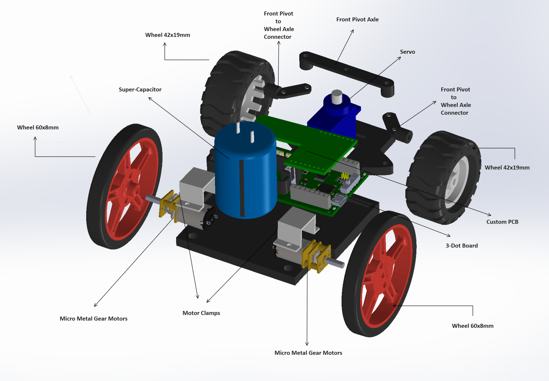
Figure 1 : Annotated Exploded View of ModWheels Generation 3
Requirements
Engineering Standards and Constraints
ModWheels is in compliance with the constraints, standards, codes, and regulations adopted by The Robot Company (i.e., CSULB) and Project Stakeholders. Specifically we include University and applicable environmental, health, and safety standards and those safety standards specifically associated with the product (e.g., Children’s Toys).
Applicable Engineering Standards
- IEEE 29148-2018 – ISO/IEC/IEEE Approved Draft International Standard – Systems and Software Engineering — Life Cycle Processes –Requirements Engineering.
- Bluetooth Special Interest Group (SIG) Standard (supersedes IEEE 802.15.1)
- C++ standard (ISO/IEC 14882:1998) – Arduino De Facto Standard
- ATmega16U4/ATmega32U4, 8-bit Microcontroller with 16/32K bytes of ISP Flash and USB Controller datasheet section datasheet, Section 18, USART.
- USB 2.0 Specification released on April 27, 2000, usb_20_20180904.zip
- Motorola’s SPI Block Guide V03.06
- American Wire Gauge (AWG) standard
Environmental, Health, and Safety (EH&S) Standards
- IEEE National Electrical Safety Code (NESC)
- NCEES Fundamental Handbook (FE) Reference Handbook
- ASTM F963-17, The Standard Consumer Safety Specification for Toy Safety, is a comprehensive standard addressing numerous hazards that have been identified with toys. In 2008, the Consumer Product Safety Improvement Act of 2008 (CPSIA) mandated that the voluntary toy safety standard in effect at that time become a nationwide mandatory children’s product safety rule.
- The National Institute for Occupational Safety and Health (NIOSH) Electrical Safety [1998][page 8] Worker Deaths by Electrocution; A Summary of NIOSH Surveillance and Investigative Findings. Ohio: U.S. Health and Human Services.
- Safe Method for Testing, Storage, and Disposal of LiIon batteries via Personal email communication dated May 9, 2018, to Gary Hill, Adjunct Professor, COE Department of Electrical Engineering, from Michael R. Kitahara, CSP, ARM-P, CHMM, Environmental Health & Safety, California State University, Long Beach
Program Level 1 Requirements
Project/Economic
Subcategories: Cost, Extensibility, Interoperability, Maintainability, Quality, Marketability, and Schedule
1.All project Schedules shall be constrained to a completion date of Wednesday May 12, 2020. Project completion includes documentation and materials purchased by or loaned to the project
2. Modwheels shall have one custom PCB that controls the charging and discharging of the super-capacitor
3. Disassemble and Reassemble of the robot will be constrained to less than 20 minutes (10 + 10 minutes)
Social and Ethical
Subcategories: Accessibility, Aesthetics, and Usability
4. To enhance aesthetics, the robot will be designed in such a way that there are no dangling or exposed wires
5. To enhance Aesthetics, ModWheels should have a paper shell cover that models and has a form factor of a Tesla Truck
Manufacturability
Subcategories: Constructibility, Size, Weight, and Power (SWAP)
6. The Size of the electronics enclosure, will be constrained to be no greater than the 3DoT board, 3DoT shield(s), and associated mounting hardware
7. ModWheels will be powered by the 3.7V RCR123A battery included with the 3DoT board
Robot Interoperability
8. All 3DoT robots will incorporate the 3DoT v9.05 or later series of boards
9. Software will be written in the Arduino De facto Standard scripting language and/or using the GCC C++ programming language, which is implements the ISO C++ standard
10. All 3DoT robots will be in compliance with the 3DoT Command and Telemetry Packet specification
11. All 3DoT robots shall be controlled via Bluetooth 4.0 in compliance with the Bluetooth Special Interest Group (SIG) Standard (supersedes IEEE 802.15.1)
Project Level 1 Functional Requirements
Project level 1 requirements define the specifications that need to be met in order to meet the stakeholders expectations.
L1.1 Modwheels will weigh no more than 200 grams
L1.2 ModWheels shall be able to drive with one wheel off the high-side of a 2 inch tall, 12 inch long sloped ramp
L1.3 ModWheels shall demonstrate a slip differential during turns
L1.4 ModWheels shall be able to reach 5.6 feet per second with boost applied
L1.5 ModWheels shall be able to traverse a loop de loop of 12 inch diameter
L1.6 ModWheels shall be be able to jump across a 2 inch tall ramp to ramp gap of length 6 inches
L1.7 Product shall be able to operate normally after turbo-boost has ended and ready to implement turbo mode again within 2 minutes
L1.8 ModWheels shall be wirelessly controlled by Arxterra Mobile App
L1.9 Mod Wheels shall navigates through obstacle course in at most 10 minutes
System/Subsystem/Specifications Level 2 Requirements
L2.1 ModWheels chassis will be no longer than 5 inches
L2.2 ModWheels will be able to traverse entire track with one battery life from the 650 mAhLi-ion battery provided with the 3DoT
L2.3 650 mAh Li-ion battery will provide power for 2 metal gear motors, 1 servo, and 1 boost converter
L2.4 XL6009 Boost will charge 12V super-capacitor
L2.5 The metal gear motors will be able to function at a 5-12V range
L2.6 The metal gear motors will draw no more than 360 mA of current (Stall Current)
L2.7 ModWheels firmware will include a slider control for steering and one custom button/widget for initiating boost
L2.8 On boost shield, the switch design must be able to handle 250 mA of current when on
L2.9 The 3DoT will be modified with 1 shottky diode for reverse current protection
L2.10 The 3DoT will be modified with a break between the 5V and 5VM line powering the serve
L2.11 Metal gear motors must be integrable with a magnetic encoder pair kit
Allocated Requirements / System Resource Reports
This document lists the mass of each component in the final ModWheels design. Unfortunately due to the PCB no functioning properly, the final design still used a breadboard for some of the turbo-boost system and resulted in the car weighing more than permitted. Fortunately, ModWheels was able to reach its targeted speed even with more weight that initially expected.
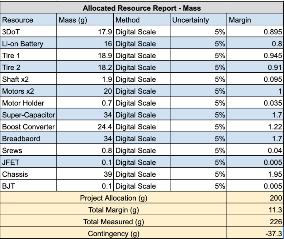
Figure 2 : Allocated Mass Resource Report
This document lists the current drawn by each major part of the ModWheels design. It is important to note that parts such as the JFET and transistor on the switch system are not listed because the current going through them is the current drawn by the motor driver when the turbo-boost mode is on.
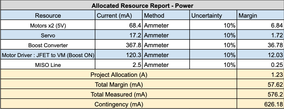
Figure 3 : Allocated Power Resource Report
Project Report
The documentation in the following section will include the WBS, PBS, and schedule.When looking at all these documents as a collective, they provide a roadmap on what the engineer should be working on throughout the year. In addition, a general overview of the ModWheels design and product will be detailed mainly in the PBS, but additional sections as well. This allows for deadlines to be met and no engineer being stuck doing no work, either on documentation, testing, etc. Lastly, there will be 2 documents for each project report, one based around the in person instruction received at the beginning of the year and the second revolving around the switch to online instruction due to COVID-19.
Project WBS and PBS
The work breakdown structure specifies each task that the ModWheels Generation #3 team had throughout the project. Specifically, the Electronics division was responsible for System Components & Design and the PCB Boost Shield Design. The Manufacturing division was responsible for 3D Modeling & Built Integration. MST division was in charge of Integration & Test and Mission & App Customization. Lastly, the Project Manager was in charge of overseeing the project and focusing on the documentation throughout the semester.
This WBS was the original document made at the beginning of the year with the thought that classes would be in person and the campus would still be open. This was valid until the course went fully online (See Waterfall Schedule).
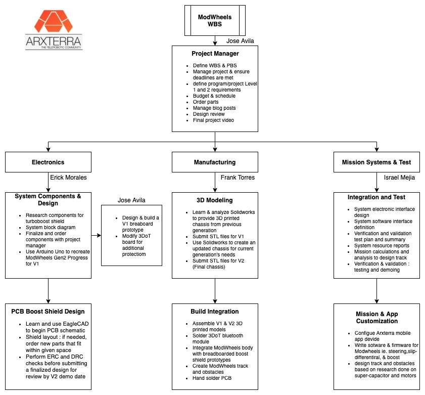
Figure 4 : Original WBS
Due to the COVID-19 pandemic resulting in classes going to full online instruction, the WBS needed to be modified. Since Israel had all the parts and components at the time of the switch, he became in charge of built integration for V2 and the design review demo in order to minimize student interactions. Since Erick ordered the custom PCB, he became in charge of soldering all the parts together instead of Frank. Lastly, since the track had not been built, Jose took the responsibility of creating the obstacle course to lessen Israel’s increased workload.
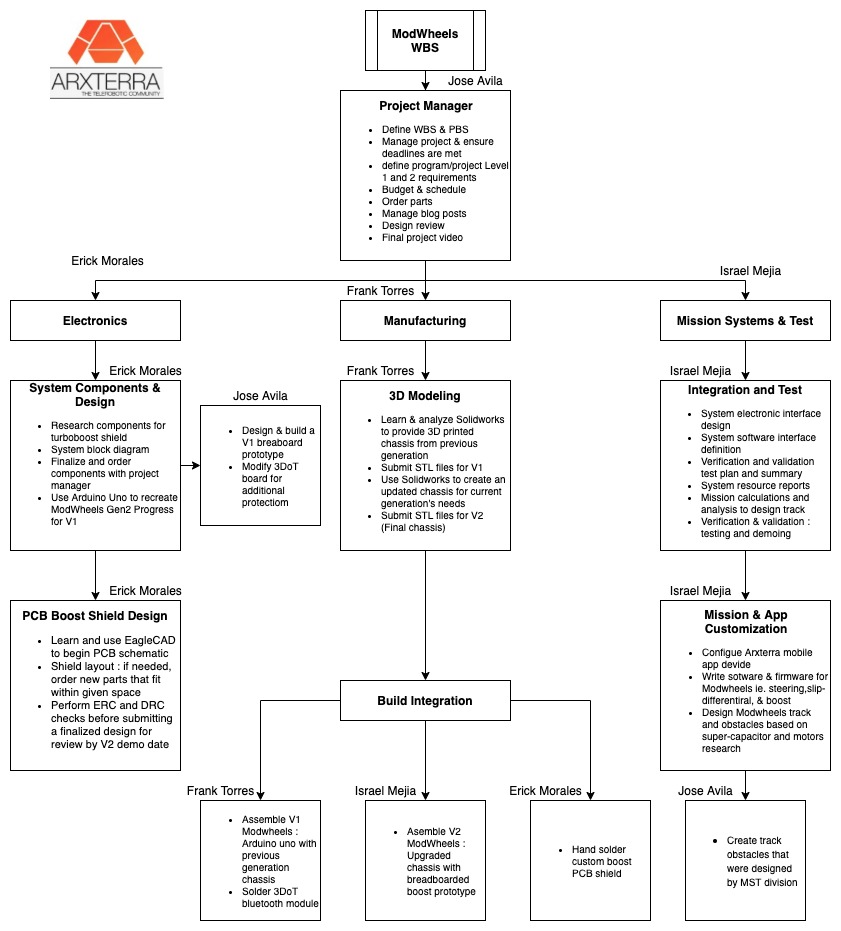
Figure 5 : WBS after course instruction went online
The product breakdown structure cites each specific component that was utilized in producing the final ModWheels Generation #3 prototype. Since the transition to fully online classes had minimal impact on our project, the PBS remained the same except for a small change with Jose Avila (PM) being in charge of the obstacle course.
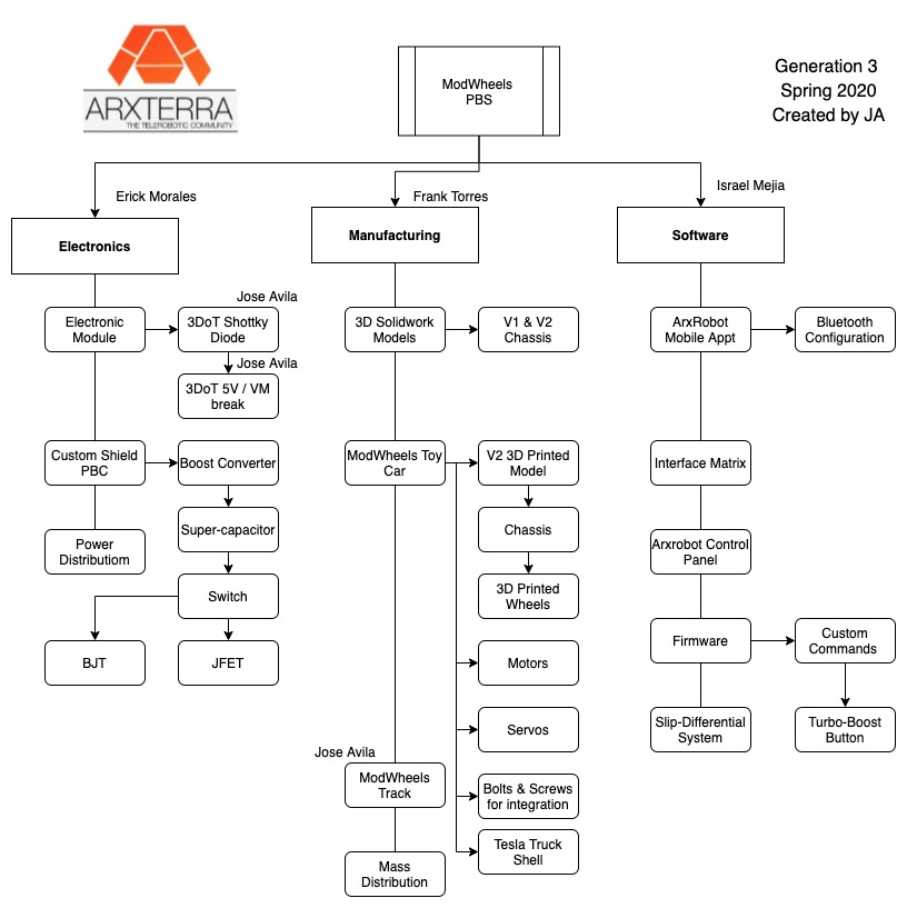
Figure 6 : Product Breakdown Structure
.
Cost
This spreadsheet details the total cost necessary to produce the ModWheels S20 product. The budget constraint was $275 which was met even after calculating for shipping and taxes. A majority of the cost came from the 3DoT and metal gear motors with smaller components accounting for the rest. Thankfully, products did not have to be repurchased, except for the 3D printings, which kept the price under budget.
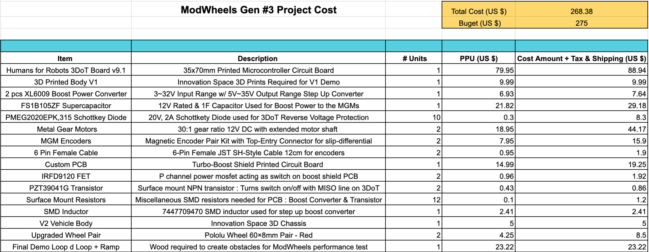
Figure 7 : S20 ModWheels project cost spreadsheet
Schedule
The waterfall schedule provides a timeline on when documentation or tasks are due. More importantly, the dates of the V1,V2, V3, & V&V demoes are provided which helped construct this timeline. Tasks from the WBS & PBS are given a loose due date for the team to follow and accomplish everything on time.
This was the original schedule that we had envisioned at the beginning of the year. This schedule was valid until 3/17.
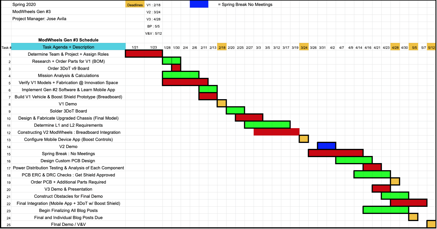
Figure 8 : Original Schedule
This was the modified schedule that was formed after went classes went fully online.
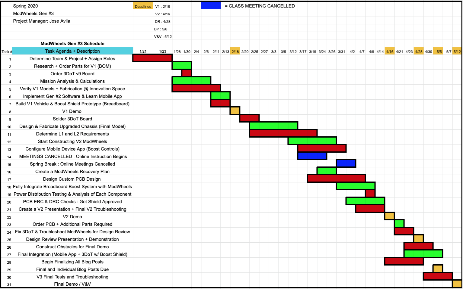
Figure 9 : Modified Schedule
Burndown and/or Percent Complete
Summary of major documentation and tasks that were required and completed by the end of the course. Unfortunately, not all requirements were met, and the percent complete reflects this by only being at 73.3%.
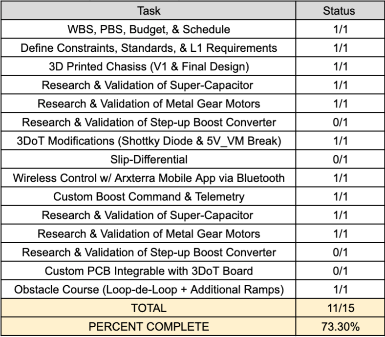
Figure 10 : Percent Complete Project Breakdown
Concept and Preliminary Design
Since ModWheels Generation 3’s main focus was speed in order to do stunts, we had to find a way to have the metal gear motors run at a higher voltage than what the 3DoT provided which was 5V. It was important to note that since we had to create a custom shield and were not allowed to simply integrate a second battery, we had to come up a solution that was more creative. With that being said, we decided to have a capacitor integrated into our custom PCB which would be charged by the 3DoT and then discharged into the motor drive. It is important to note that the 3DoT RAW line would not be able to charge the super-capacitor to the voltage desired so some sort of step up buck-converter was going to be implemented to the custom PCB as well. Lastly, We would have a switch system to allow user control over this “turbo-boost” mode aka moment in time that the motors would be running at whatever the capacitor voltage was. Therefore it was crucial to pick the appropriate capacitor to not burn out any 3DoT components and analyze the 3DoT to see if we could modify it and add further protection from our Turbo-Boost shield.
Using the 3DoT schematic provided by the humansforrobots website, we created the blueprint to how our custom PCB design was going to integrate with the 3DoT.
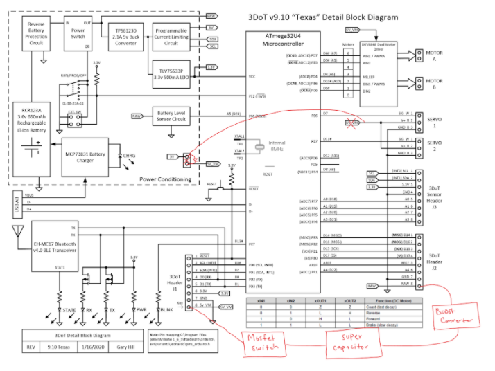
Figure 11 : Turbo-Boost Shield Preliminary Design
Literature Review
One of the first theoretical calculations that drove our entire design process was the velocity needed to traverse a loop-de-loop. This was our final goal for this project which tied well with trying to make our version of ModWheels the fastest to date. If our toy-car was not fast enough, there would be no chance of getting across the loop-de-loop obstacle. These calculations provided a reference point to see how well our turbo-boost shield was being designed. Down below, we modeled and charted the speeds necessary to traverse a loop-de-loop with a given radius.
We quickly found out that the speed required to traverse a loop-de-loop was V = (radius*gravity)^(1/2). This was modeled in Matlab.
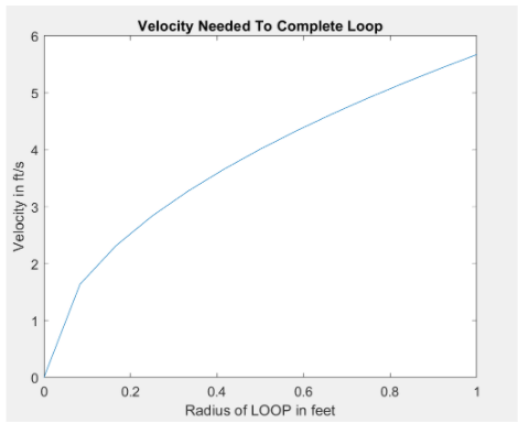
Figure 12 : Matlab Plot of Velocity Needed to Complete a Loop
In addition, we charted some of the most notable radius sizes and speeds we thought that Modwheels was able to accomplish following testing from the V1 Demo.
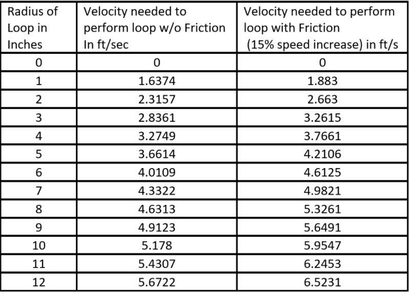
Figure 13 : Chart of Different Radius Sizes & Velocity Needed to Perform Loop
Design Innovation
ModWheels S20 Aims to implement all these innovations:
- Additional 3DoT reverse current protection
- Smaller & lighter 3D printed chassis
- Magnetic MGM encoders for differential
- Custom turbo-boost shield
- Step-up boost converter to charge super-capacitor
- Switch system to discharge capacitor into motor drive
- Turbo-boost custom command on Arxterra Mobile App
Conceptual Design / Proposed Solution
Conceptually in the most basic terms, we are charging up a super-capacitor and after some time, unloading the built up charge into the motor drive allowing the motors to run at a higher voltage than the 3DoT is capable of (5V). It is important to note that the super-capacitor rated voltage must be high enough to create a substantial motor RPM increase while being low enough to not burn out any components. With that being said, we chose a 12V super-capacitor (See Research & Trade Off Studies : Capacitor & Metal Gear Motors) that was charged by the 3DoT RAW line which was then stepped up to 12V by an adjustable XL6009 boost converter. To make sure this proposed solution was possible, for V1 we created a basic breadboard prototype with all the components mentioned and attached 1 motor to act as the load. If this initial design worked and we saw the motor RPM increase, we were confident that we would be able to translate the core of the design into a custom turbo-boost PCB.
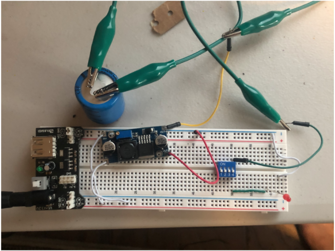
Figure 14 : V1 Turbo-boost breadboarded prototype
With an Arduino power source, we were able to use the XL6009 boost converter and charge up the 12V super-capacitor. Once fully charged, we used a dip switch to discharge the current into the metal gear motor (off screen). Once switched on, which would eventually become our turbo-boost mode, we saw that the metal gear motor RPM increased significantly. Since the core and concept of the design worked, we were able to move forward and start integration with the chassis and 3DoT. This eventually would lead us to create a custom turbo-boost shield.
System Design / Final Design and Results
For the final design, there were no drastic changes to the boost shield design. Besides moving from from a breadboarded prototype to a fully soldered custom PCB, most of the components remained the same. Initially, we were going to use SMD buck-converter instead of the large XL6009 breadboard boost converter to space on the shield. Unfortunately we could not find an appropriate component that would boost 3V to 12V with a 1F capacitance load so we stuck with the XL6009. Therefore to save space, we desoldered the XL6009 and placed all the components in a more fitting manner in respect to our custom PCB. In addition, instead of using a DIP switch to turn on/of turbo-boost mode, we used a high-side FET power switch that was wirelessly controlled through the MISO line and an Arxterra Mobile App custom widget. As far as components related to the custom PCB, we kept the 12V super-capacitor consistent throughout the design process. Lastly, since the 5V_VM line was connected to the servo and the 5V line, modifications to the 3DoT board were required. First of all, we needed to break the connection between the 5V_VM line and the servo because when the super-capacitor was charging, we did not want the servo to run at 12V. After the break, we jumped a wire over from the servo to the 5V line so it could still be powered on. Lastly, we added a shottky diode for reverse protection between the 5V and 5V_VM line to make sure our 3DoT would remain undamaged after the turbo-mode was activated. All the details of our design can be seen in the individual blog posts and the electrical design section of this final blog post.
Unfortunately, when we soldered our custom PCB the XL6009 boost converter was not stepping up the raw 3V to 12V. This meant that we could not use the PCB in the final demo and were forced to use the breadboarded version of out turboboost system. All the components excluding the custom PCB that were mentioned are shown in the picture below
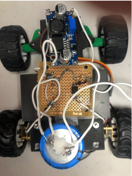
Figure 15 : Final Design Due to PCB Failure
System Block Diagram
The 3DoT board component is composed of the battery which supplies power to the Boost Shield. It also contains an EH-MC17 Bluetooth which is used to communicate with the Arxterra App installed on our phones. A modification unique to ModWheels is our connection from power conditioning to the Servo rather than the 5V_VM. Using the MISO signal in the 3DoT we are able to send control the switch on the Boost Shield turning on and off our boost. From the switch, the 12VDC is inputted into the DRV8848 Motor Driver of the 3 DoT board to drive the motors at the speed we desire.

Figure 16: System Block Diagram
Interface Definition
Our interface matrix shows the connections between the 3DoT board and the TurboBoost shield. The RAW signal is the input to the shield which takes that voltage and steps it up to the desired 12VDC. The output of our shield is the drain of the mosfet we used to implement the high-side switch and connects to the 5V_VM signal of the 3DoT board.
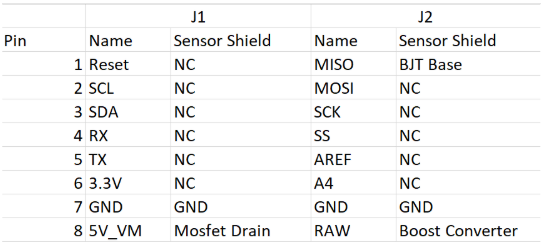
Figure 17 : Interface Matrix
Modeling/Experimental Results
All modeling and experiments done throughout the course were turned into individual blog posts which detailed each engineers process in accomplishing their assigned tasks. An overview of what modeling and/or experiments were completed can be seen in the chart below and a direct link is given to access each specific blog post.
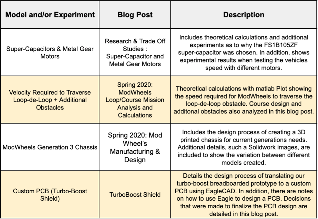
Figure 18 : Chart Providing an Overview of Which Blog Posts Provides Information on a Specific Model or Experiment
Electronic Design
The boost converter used in our design was the XL6009 which is capable of boosting the RAW voltage to 12VDC. This boost converter was a good choice because it has a wide input range and was easily tuned by changing the resistance network which connect to its feedback pin.
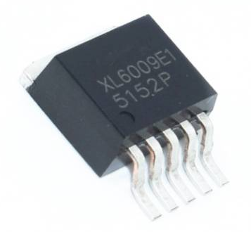
Figure 19 : XL6009 Boost Converter
The second main component of our electronic design / custom PCB was the FS1B105ZF. It is a 12V,1F capacitor that is going to be charged by the XL6009 cost converter and with a switch system controlled by the arxterra mobile app, was going to discharge its built up charge directly into the motor drive. This was would mean the motors would be running at 12V for a short moment instead of the 5V provided by the 3DoT which would result in a speed increase, or as well called it, a “turbo-boost'”. It was important to choose the appropriate super-capacitor or else it would potentially burn out the 3DoT or more specifically, the motor drive. Additional modifications of the 3DoT board was required. All the details were discusses in the Research & Trade Off Studies : Super-Capacitor and Metal Gear Motors blog post.
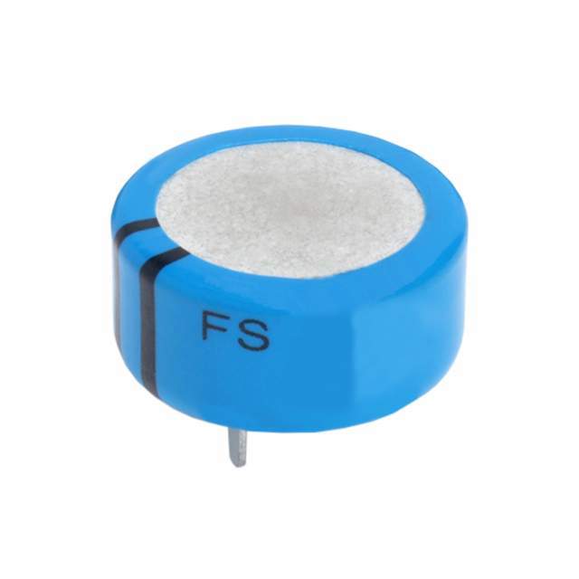
Figure 20 : FS1B105ZF Super-Capacitor
PCB Design
The PCB consisted of three components: Boost Converter, Supercapacitor, and High-side Switch. We see all three in our rapid prototype phase on the breadboard and a much more detailed schematic of how the components are connected together. The eagle model shows the board layout showing the P shaped board we designed to fit in the 3DoT. The final image shows the soldered PCB containing mostly surface mount devices.
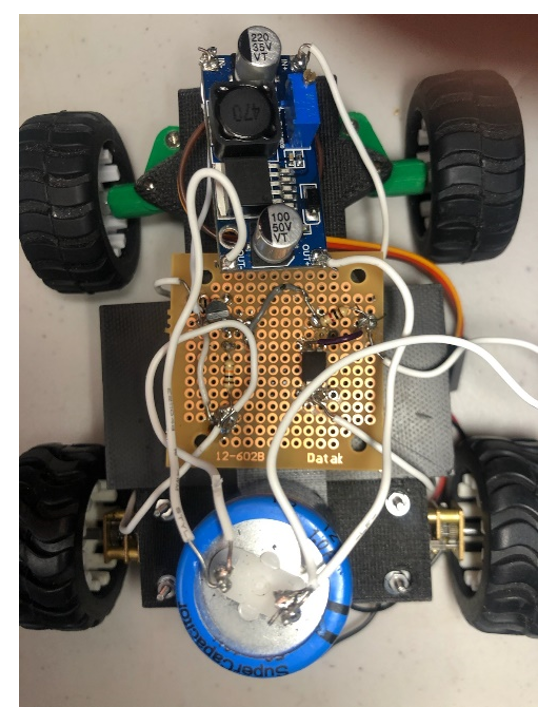
Figure 21 : Breadboard
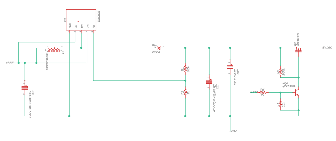
Figure 22 : Schematic
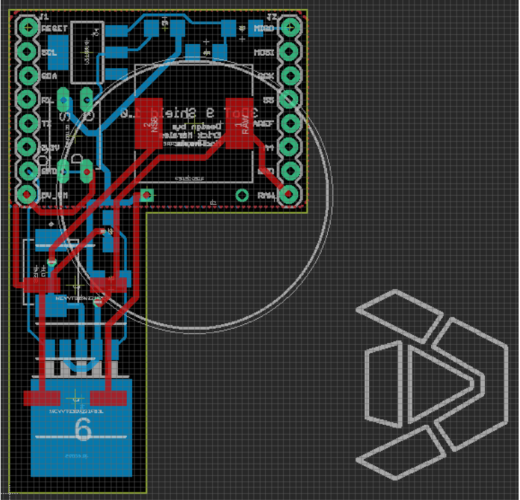
Figure 23 : PCB Layout
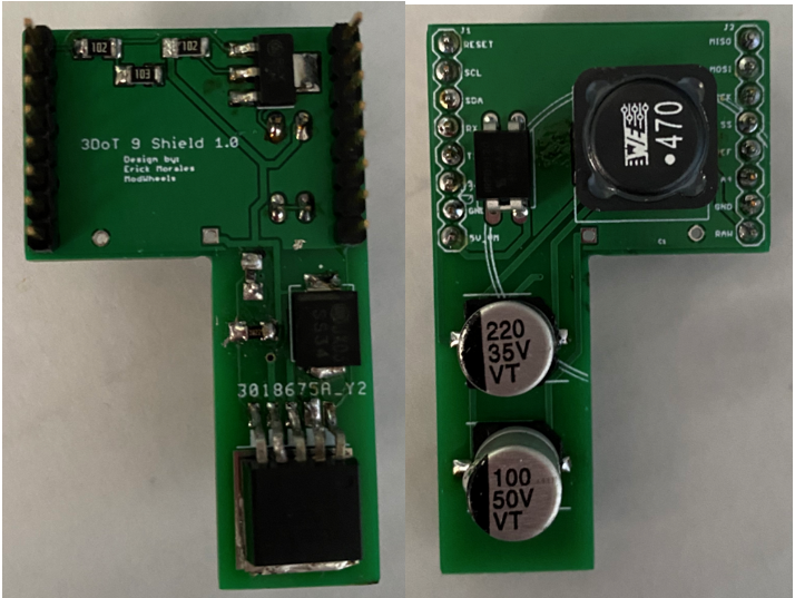
Figure 24: Soldered PCB
More information on the TurboBoost Shield can be found here.
Firmware
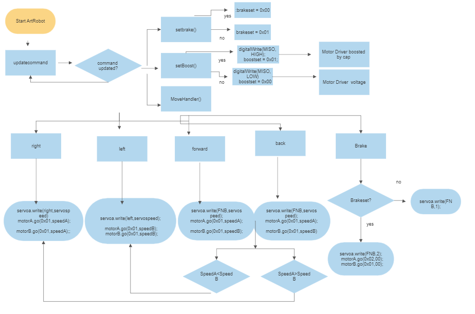
Figure 25 : Software Block Diagram
// creating our custom brake and boost commands
#define Boost 0x41
#define Brake 0x42
uint8_t boostset = 0x00;
static uint8_t brakeset = 0x00;
const uint8_t CMD_LIST_SIZE = 3;

bool setbrake(uint8_t cmd, uint8_t param[], uint8_t n)
{
  if (param[0] == 0x01) brakeset = 0x01;
  else brakeset = 0x00;
  return false;
}

// boost handler
bool setBoost(uint8_t cmd, uint8_t param[], uint8_t n)
{
  if (param[0] == 0x01){
    digitalWrite(MISO, HIGH);
    boostset = 0x01;
  } else {
   digitalWrite(MISO, LOW);
   boostset = 0x00;
  }
  return false;
}
using our arxterra app we used our custom telemetry commands to implement out boost switch. This is used using boolean and is activated by a simple switch on the axterra app giving the ability to turn on and off the boost and auto brake features. After that we override the movehandler in order to get full control of the servo angle and motors controls.
// Set encoder as input with internal pullup
pinMode(SCL, INPUT_PULLUP);

// Attach interrupt
attachInterrupt(digitalPinToInterrupt(SCL), updateEncoderL, CHANGE);
pinMode(SDA, INPUT_PULLUP);

// Attach interrupt
attachInterrupt(digitalPinToInterrupt(SDA), updateEncoderR, CHANGE);

// Setup initial values for timer
previousMillis = millis();
previousMillis2 = millis();
we setup our encoders with a pullup in order to not get any noise and get more accurate readings. then we attach both of these to a interrupt so we can have constant count of the “ticks” sent by the encoder to be converted to rpm values.
// Update RPM value every second
currentMillis = millis();
if (currentMillis - previousMillis > interval) {
previousMillis = currentMillis;

// Calculate RPM
rpmL = (float)(encoderL * 126 / ENC_COUNT_REV);

// Only update display when there is a reading
if (rpmL > 0) {
 Serial.print(" PULSES: ");
 Serial.print(encoderL);
 Serial.print('\t');
 Serial.print(" SPEEDL: ");
 Serial.print(rpmL);
 Serial.println(" RPML");Serial.println(" w");
 Serial.println(W3);
 Serial.println(W4);
 Serial.println(rpm);
 Serial.println(xspeed1);
}
 encoderL = 0;
}

This code then takes the "ticks" counted and turns them into rpm values depending on the gear ratio.

// calculating rpm per motor differential speed

if(thetaset>FNB) answer = thetal * 3.14159 / 180;
// calculating rpm per motor differential speed
if(xspeed1==0) xspeed1=0;
else xspeed1=xspeed1-1;
   :
if (rpmR
Rpm of the motors coming from the encoder data is then compared with the calculated rpm values with a if statement and depending on if the motor is slower of fast then the desired rpm value then we will increase or decrease the speed of the motors.
Our final code include the parts for the differential drive and encoder reading but due to the inability to get both encoder to work simultaneously testing of the differential drive was difficult. But the code for differential drive calculation and  encoder reading work on their own. Encoder code issue one encoder is left without data when reading simultaneously.
Mechanical/Hardware Design
Final design key features of overall project:
- Chassis Length: The 4.66 inch chassis allows for a greater chance of accomplishing our mission of completing a loop.
- Chassis Material: Onyx/Carbon-Fiber chassis made to be light weight yet durable to withstand collisions without damaging the chassis.
- 3Dot Pocket: Allows the 3Dot to fit in a 1/8 inch deep pocket created at the center of the chassis for protection and center of mass.
- Larger Rear Tires: This allows to achieve greater distance per rotation therefore increasing our speed which is crucial to our design.
Steps in designing my chassis can be seen here...
The Final Design
The following images showcase the V2 chassis that was also used for V3, a complete annotation of our final V3, and the how I would've wanted our V3 chassis to look like if we had access to the innovation space.
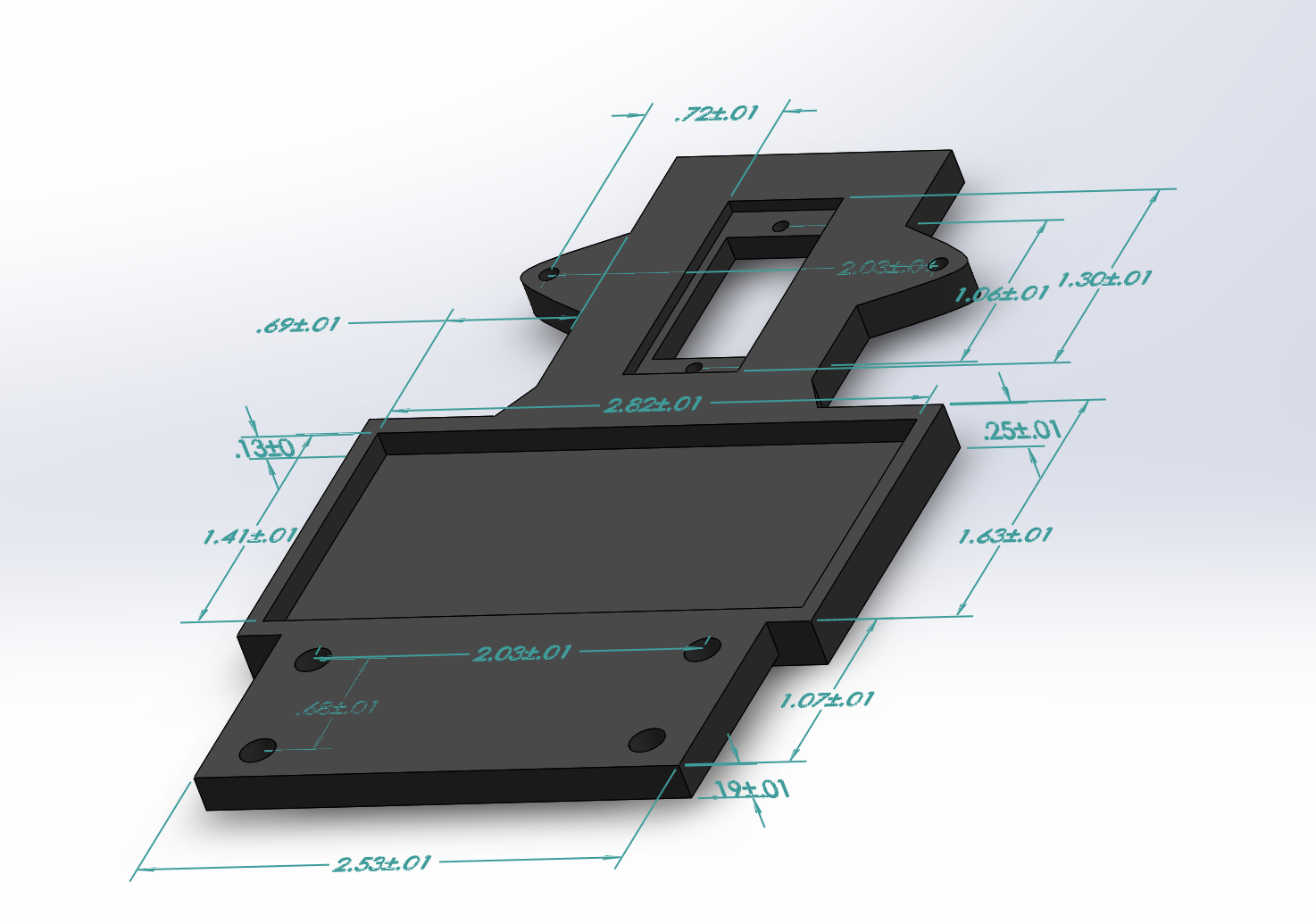
Figure 26 : V2/V3 Chassis

Figure 27 : V3 Annotated Exploded View
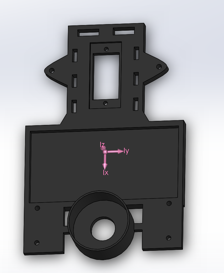
Figure 28 : How our chassis would've looked if we had access to Innovation Space
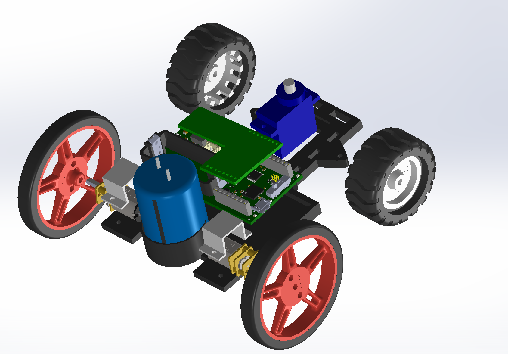
Figure 29 : How our exploded view of our V3 would've looked like if we access to Innovation Space
Overall the chassis and other key designs made to this generation of Mod Wheels were great modifications fit for our mission. If we had access to Innovation Space I would've liked to print out the new chassis created. The new chassis is lighter and has a better center of mass location that could potential increase our chances of having a better model for our Mod Wheel Generation #3.
This section includes all SolidWorks generated 3D Models of the design. Annotation is recommended. If available the Manufacturing Engineer include photos of the Prototype/Production Parts.
Verification & Validation Test Plan
After the course switched to fully online instruction due to the COVID-19 pandemic, the lost time resulted in only creating a verification test plan. The verification test plan was split into 4 test cases to assess each constraint, standard, and L1 requirement. The performance of this generations ModWheels can be found in the Verification Test Plan found here.
Concluding Thoughts and Future Work
Overall the group did not accomplish everything we set out to do but got very close which the next generation can build upon. First of all, finding an improved and functional component for the step-up boost converter would be the first thing to do. With this, the turbo-boost mode should be functional and alterations of the product can occur. One of the issues we had was the slip-differential not working properly because the encoder would only read 1 motor at a time. Fixing this small error accompanied with an effective turbo-boost would debug all the design flaws we encountered. As far as unique adaptions, making a custom widget displaying the charge level of the super-capacitor would benefit the user because they would know when the turbo-boost mode was available. Potentially adding sounds and/or lights for when the turbo-boost was on would enhance the aesthetics and create a more realistic toy-car. Lastly, if a group wanted to start a brand new project, the turbo-boost design could be applied to many other objects, such as a toy-boat where there is a desire to have two speeds for the robot, standard and turbo.
References/Resources
These are the starting resource files for the next generation of robots. All documentation shall be uploaded, linked to, and archived in to the Arxterra Google Drive. The “Resource” section includes links to the following material.
- Project Video YouTube
- Design Review
- Project Libre (with Excel Burndown file) or Microsoft Project File
- Verification Test Plan
- Solidworks File
- EagleCAD files (zip folder) Linked to in Electronics Design Blog Post
- Arduino and/or C++ Code (zip folder) Linked to in Software Design Blog Post
- Complete Bill of Materials (BOM)