MicroFobo Generation #4
Final Blog Post
Authors: Dakarai Scott, Fabio Mendoza, Hien Nguyen, Jeffrey Macahilig
Table of Contents
Executive Summary
Ever since man has first looked into the sky, he has dreamed of one day walking among the stars. As our technological advancements advanced we have gained the ability to send men to the moon and robots to Mars. As the next step to realizing that age-old dream we will one day send an astronaut to walk the surface of the red planet. This robot is a pivotal step in becoming the spaceward species we know we can be.
Program and Project Objectives
Program Objectives
The National Aeronautics and Space Administration (NASA) will be debuting its revised Project Biped robots and its new Perseverance rover at the Jet Propulsion Laboratory (JPL)in Pasadena CA on May 14, 2020. Your team’s assignment is to make the 3D printed and/or laser-cut prototypes to be showcased at the convention, prior to production starting in the second quarter of 2020. The Project Biped robot will feature our new ArxRobot smartphone application and the Arxterra internet applications allowing a test of the robot from the Command Center. In addition, the robots should be able to operate autonomously in rove mode. See mission(s) (i.e, mission objectives) assigned to your robot by the Exploration Division. To decrease electronics cost, interoperability between all NASA robots will be maintained by incorporation of the 3DoT board, developed by our Electronics Research Center. Modification of downloadable content is limited to software switch setting and robot unique graphics of the smartphone and Arxterra applications. Modifications of electronics are limited to custom 3DoT shields as required by the unique project objectives of your robot. The Media Contacts and Information center has agreed to recycle our Project Biped robot as public technology following testing. To decrease production costs, please keep robots as small as possible, consistent with our other objectives. As with all our products, all safety, environmental, and other applicable standards shall be met. Remember, the American taxpayers, are our most important stakeholders. Our Applied Manufacturing Division has also asked me to remind you that Manufacturability and Repairability best practices must be followed.
Project Objectives
NASA’s Planetary Science Division has decided to send another exploration robot to Mars. After the Curiosity rover’s final mission, NASA seeks to explore the terrain of Mars from the perspective of our pioneering astronauts. To test the density and irregularity of the planet’s surface, the robot to be sent is a bipedal robot. This robot will be capable of covering traverse terrain that the previous rovers were unable to acclimate to. Additionally while simulating the actions of an astronaut, this new robot will be testing the bounds of mobility and different modes of locomotion whilst completing its mission of finding geographical locations on Mars.
This new robot will be named MicroFOBO.
Mission Profile
To demonstrate the effectiveness of this prototype’s maneuverability, MicroFOBO will need to complete 3 trials. In our first trial, the robot will demonstrate the ability to walk and turn autonomously. This is a test of hardware functions and the robot’s systems. The second demonstration will simulate a live test from the ground. MicroFOBO will be tested on its reaction to delay. During this time, the robot will be prompted to walk forward, turn right, and turn left and will be assessed on its subsequent responses. The final trial will consist of testing its ability to walk on its own, after a controlled walking sequence to the testing location. The plaque’s location will be transmitted from a long-distance sensor which will relay the angle remotely. These angles will then be sent to the walking MicroFOBO’s control panel and it will turn the angle that was entered and approach the plaques, which represent the geographical locations on the surface of Mars.
Requirements
Engineering Standards and Constraints
L1.1 This project shall be constrained to a cost of $450.
L1.2 This project shall be completed by May 14th, 2020.
L1.3 Firmware programs will be written using Arduino De Facto Standard.
L1.4 MicroFOBO shall incorporate the 3DoT v9.05 or v9.1
L1.5 MicroFOBO shall contain one custom-designed 3DoT shields.
L1.6 MicroFOBO shall weigh less than 1000 grams
L1.7 MicroFOBO shall be controlled via Bluetooth 4.0 in compliance with the Bluetooth Special Interest Group (SIG) Standard.
Project Level 1 Functional Requirements
L1.1 MicroFOBO is based on the Project BiPed FoBo robot. The MicroFobo project, like Fobo will use 8 servos.
L1.2 MicroFOBO shall be controlled by the user through the Arxrobot application control panel for the duration of the mission.
L1.3 MicroFOBO shall incorporate operating modes that allow the user to intercept the movement of FOBO while in automatic mode.
L1.4 MicroFOBO shall transition to a stable standing position when it is not being told to walk forward in manual mode. (walk to stand)
L1.5 When the autonomous walking algorithm is employed MicroFOBO shall continue walking forward until it sees a plaque and then stops within 25 cm.
L1.6 Plaques will be placed between 0.3 to 1 meter, from MicroFOBO’s initial position.
L1.7 The distance between any two plaques will be between 25 cm and 1 meter.
L1.8 Plaque faces of the 2 closest plaques shall be rotated no less than 5 degrees and no more than 90 degrees from the reference plaque’s orientation.
L1.9 While the autonomous walking algorithm is employed MicroFOBO shall execute a right turn after a plaque has been detected.
L1.10 MicroFOBO shall be able to complete a turning sequence in less than 7 seconds: 30 degree +/- 2 degrees.
L1.11 MicroFOBO shall be able to complete a 360-degree scan of its surroundings by using the scanning unit in the head.
L1.12 The scanning unit shall be able to map surroundings by detecting a minimum of 4 out of 6 plaques.
L1.13 MicroFOBO should be able to implement a moon walking motion.
System/Subsystem/Specifications Level 2 Requirements
L2.1.1 MicroFOBO shall use metal gear servo motors with an input voltage of above 5V.
L2.1.2 The metal gear servos shall be capable of producing at least 0.58 kg*cm of torque while under full load.
L2.2.1 MicroFOBO shall use a custom 3 DoT shield designed for 8 servos, 1 Lidar and 1 stepper motor.
L2.2.2 MicroFOBO will use the ArxRobot application’s joystick function to control forward and turning movements.
L2.7.1 The scanning unit shall be comprised of a distance sensor and a revolving device.
L2.7.1 The distance sensor will be capable of quick data acquisition to detect as many points as possible.
L2.7.2 MicroFOBO shall utilize a distance sensor capable of sensing an object from as close as 25 cm to a distance of 2 meters from the lens.
L2.8.3 The distance sensor shall not be in excess of 11 grams.
L2.11.1 MicroFOBO will use an ultrasonic, TOF or a Lidar as a distance sensor.
L2.11.2 MicroFOBO shall utilize either a stepper motor or a rotary encoder to revolve the chosen distance sensor while mapping it’s surroundings.
L2.11.3 The stepper motor or rotary encoder shall be able to rotate in increments of 0.01 degrees at minimum.
L.2.11.4 The stepper motor or rotary encoder shall not be in excess of 40 grams.
Allocated Requirements / System Resource Reports
The total calculated mass of the completed robot is 607 grams. This mass results from the mass of each component. The most sizable components provide the most mass to the robot’s build. Since the robot will require at least 3 batteries, this mass is a large portion of the final product second only to the mass of the servo motors.
The final product provides power to 8 servo motors, a 3DoT board, a stepper motor and a lidar distance sensor.
The design of the custom servo shield was determined by the current draw of the servos, the lidar and the stepper. The 3DoT board will be powered by a separate power supply than the servo shield.
For further explanation of the power requirement on the servo motors continue to the post: https://www.arxterra.com/servo-trade-off-study/
Project WBS and PBS
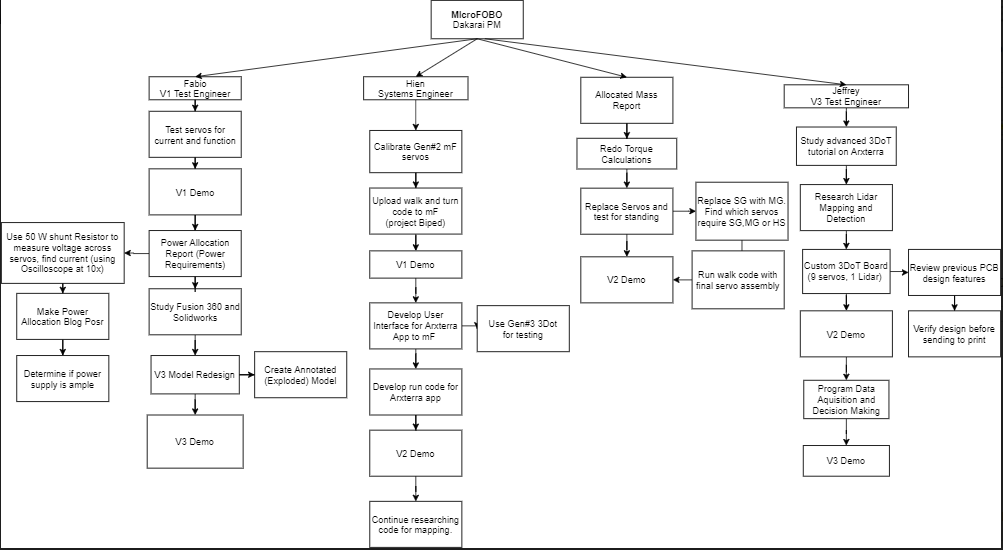
The work breakdown structure describes the individual tasks of each of the project’s engineers. As the project progressed the work breakdown structure changed to reflect the availability of materials in each contributor’s vicinity.
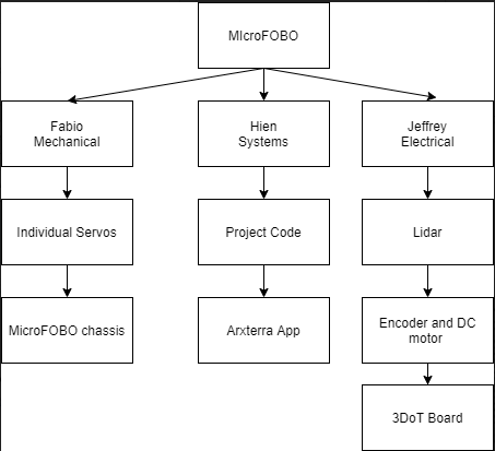
The product breakdown structure defines the subsystems of the final robot and which engineer will be responsible for its completion.
Cost/ Updated Budget
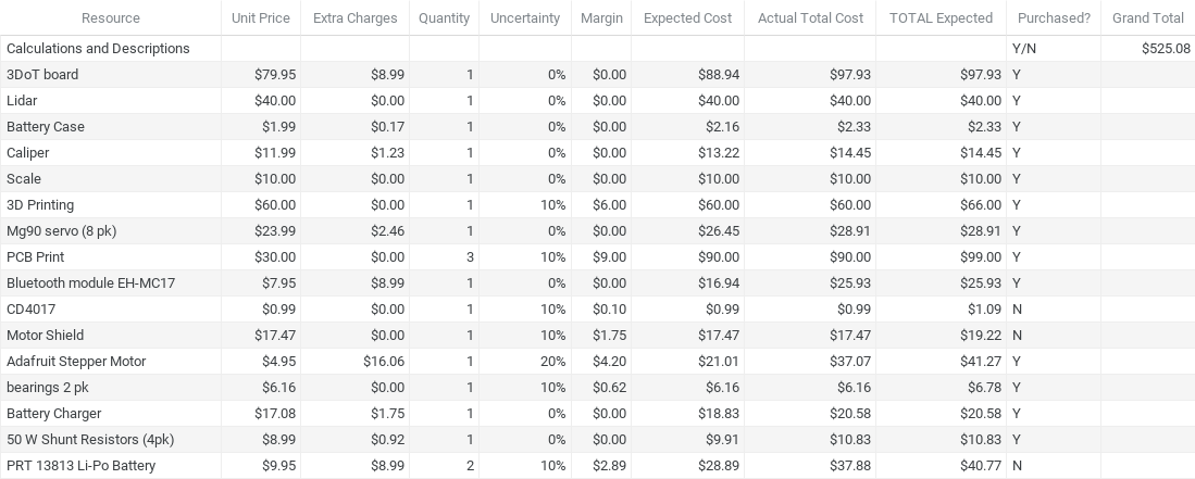
The completed project is estimated to be $450. This projected cost is estimated from software and hardware costs from all versions of MicroFOBO.
The following shows the total cost expected for building MicroFOBO generation #4.
The following reflects the changes to the budget as the semester progressed. The inability to 3D print resulted in a estimated $60 reduction in the original budget.
Since generation #4 MicroFOBO inherited a number of components from generation #2 and #3, it was possible to remain within the cost restraint given for our project.
Schedule
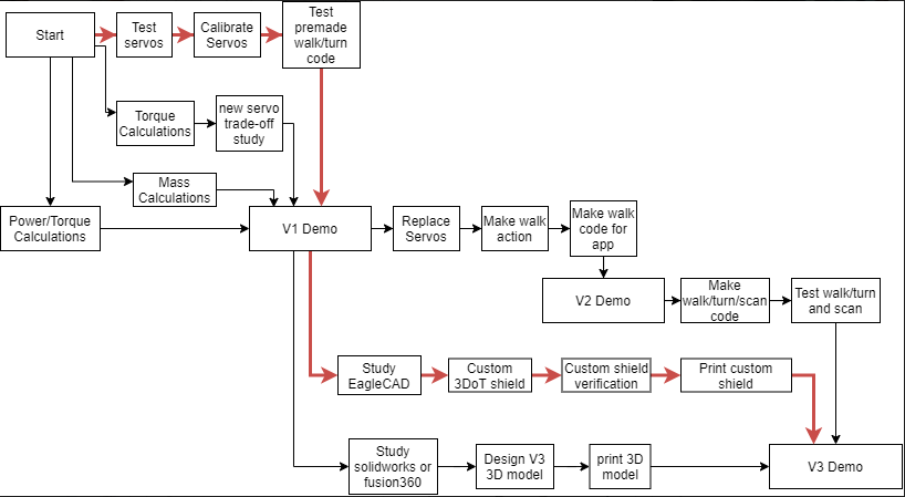
This waterfall diagram shows which responsibilities that must be completed and in the order necessary to compete the mission. The waterfall diagram is 95.45% complete. The responsibility that was not completed, namely print 3D model, was not completed due to a shift in design planning following the closing of the 3D printing facility.
Concept and Preliminary Design
MicroFOBO was originally designed by the Spring 2018 project team to be a miniaturized version of a robot called FOBO which was created by Jonathan Dowdell at Project Biped. The Spring 2018 team was task with scaling the robot down to approximately 60% of FOBO’s original design and making FOBO walk. The Fall 2019 team was tasked with completing a new servo shield for FOBO. In all previous iterations of FOBO, the task of completing its walking action has been unsuccessful.
In our version of MicroFOBO we have seen the first instance of FOBO walking since the beginning of MicroFOBO design.
Literature Review
The most significant literature for design and planning has been Arxterra. This reference was useful for determining the structure for planning tools such as schedule, WBS, PBS, cost, budget, requirements and constraints.
For building FOBO the literature most significant has been the Project Biped website. (Found here http://www.projectbiped.com/) As the project started the resources on the Project Biped website include but, are not limited to: demo walk files, demo turn files, navigation files, FOBOposer project videos.
The Project Biped files were used primarily to get FOBO walking in the first demo. There the walk files were generated and served a reference for the following demos. For further explanation on the adaptation of the original project files to the final project files see the Firmware section below.
Design Changes
The changes to the mechanical design are as follows: a smaller neck, a removable face, a neck, component housing, and long feet. These changes make a walking and scanning FOBO possible and will be explained in more detail in the Mechanical Design section. The electronic design required an upgrade as well. Most notably the integration of a stepper motor for a rotating head a stepper motor for improved data acquisition.
Lastly, this project required numerous changes to the firmware and interface. The interface included the Arxterra application just as the previous generations, however, this new FOBO required several operation modes such as an autonomous walking function, a walking while scanning function and a R/C mode as well.
System Design / Final Design and Results
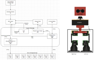
The system of MicroFobo consists of a user interface that is used in the Arxterra App. This Arxterra App is attached to the 3DoT board through the bluetooth module of the 3DoT board. A custom shield is added onto the 3DoT board to control the 8 servos, stepper motor, and lidar. This generation of MicroFobo differs with the stepper motor and lidar being added onto the custom shield. The wiring of the PCB is also different in that the external power supply does not power the CD4017 counter on the board. The reason the CD4017 is powered by the 3DoT board is to reduce any possible noise that can be caused by connecting the entire system to one power supply.
System Block Diagram
The system block diagram has numbers for where each component lies on the MicroFobo robot. MicroFobo consists of a servoshield (06). This custom shield is connected to several components being the 3DoT Board (03), Stepper Motor (08), External Battery (05), and eight servos (07).
Modeling/Experimental Results
MicroFobo was modeled in Fusion 360. The main adjustments were made on the foot and slight alterations to the servo bands. With respect to the upper portion of MicroFobo, most of the parts were created from scratch. Looking back at all of the previous models we were the first to not house all of the components inside the head of Fobo. Our team decided it would be best to design a housing where we can store the 3Dot board and mount our stepping motor onto it.
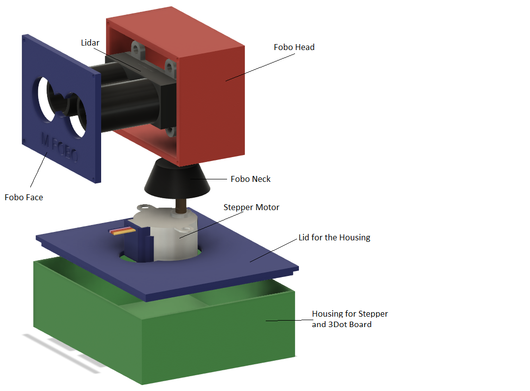
Presented above is the upper portion of MicroFobo. As you can see the head has been significantly resized to only house the lidar. Next we Implemented a neck where the head would rest and house the shaft of the stepper motor on the bottom. The stepper motor will be mounted on the top of the lid of the housing to allow the shaft of the motor to show. Finally, the housing unit at the bottom to house the 3Dot along with servo cables.
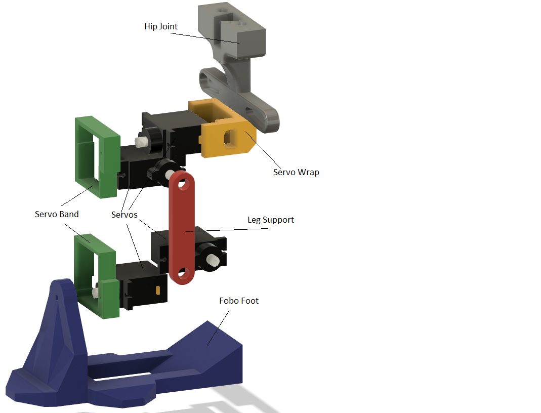
The bottom portion of Fobo did not have as many modifications as the top, but still were just as important. The servo bands had to be resized in order to have the servos fit snug so the only movement will occur at the gears. The feet of fobo also had some alterations to them. The team thought the most ideal place to mount our power supply would be at the feet of fobo. In order to mount the batteries the feet would have to be longer to allow the batteries to securely fit on top
Unfortunately, given the circumstances during the semester, we could not 3D print the parts to officially confirm the parts would be a perfect fit. However, there is a website called “grabcad.com” where we can grab parts that have been previously created. These created parts are built to scale meaning if the parts fit and mount nicely in Fusion 360 we can confidently assume the parts would have worked.
Mission Command and Control
For our generation of MicroFOBO, there are 3 different versions of software, each for V1, V2, and V3. For V1, the functionality of MicroFOBO is demonstrated using an Arduino UNO and an ultra-sonic module. The software for V1 requires a “Servo_Shield.h” library which can be found from the Project Biped website. This version of MicroFOBO is fully autonomous and will walk straight until it detects obstacles in its path, then will execute a right turn to avoid the obstacle and carry on the walk action. Most of the software in this version is referenced directly from the Project Biped website called “Navigation”.
For V2, in compliance with our constraints, MicroFOBO incorporated the 3DoT v9.1b board in replacement of the Arduino UNO. The software for this version requires a modified version of the original “Servo_shield.h” and the ArxRobot library. Since the 3DoT and the Arduino UNO uses different microcontrollers, some modifications has to be made for the “Servo_Shield.h” for it to work with the 3DoT. Fortunately, we were able to work with the modified version of this file from last iterations of MicroFOBO which saved a lot of time and effort. This version of MicroFOBO is controlled wirelessly via Bluetooth through the ArxRobot App. MicroFOBO’s movements are fully controlled via the D-pad of the App. In “void loop()”, the “ArxRobot.loop()” takes in user input from the d-pad of the application with “param[0]” to “param[3]”. The function “moveHandler()” translates these param[]s into different “stateActive” which determines the corresponding “currentAction”. Finally, “UpdateAction()” and “NextFrame()” takes in values of “currentAction” and output the according action frames from the defined action class.
For V3, we initially planned V3 to work with a Lidar module to carry out our mission. However, due to the COVID-19 situation, we were not able to fully incorporate the Lidar module into MicroFOBO and instead created user input in the ArxRobot controls to simulate this interaction. In this version of MicroFOBO, we can remotely control its movements with the ArxRobot Application similar to V2 mission command and control. At the same time, elements of V1 to autonomous operation and detect obstacle is also incorporated. As mentioned above, the Lidar module is incorporated by simulating user input to control MicroFOBO. The new function “operationHandler()” takes in user input and decides the mode of operation for MicroFOBO and the “anglesHandler()” simulates the environmental data translated from the Lidar module for MicroFOBO to map its path and carry out its mission.
Fig 1. Software block diagram for V3
Electronic Design
PCB Design
For a complete description of the PCB design follow [link]
Firmware
For our generation of MicroFOBO, we used the FOBOPoser program to calibrate, create actions and generate codes for MicroFOBO and the ArxRobot App to control MicroFOBO via Bluetooth. You can find detailed information about our firmware here
Mechanical/Hardware Design
The first component to be redesigned was the Head of MicroFobo. Previous iterations of MicroFobo utilized the head to house all of its components. The team decided it would optimal if the head would only house the lidar. Initially, I thought it would be quick to simply redesign the previous file of Fobo’s head. However, when the file was transferred into Fusion 360, the component had too many faces within the part and would take a long time to prep and modify. To save time I made the part from a fresh sketch and modeled it with respect to the lidar. The face of the head of Fobo can come off just in case the lidar needs to be worked on. On the back of the head, there is an opening to allow the wires of the lidar to come out and connect to its custom PCB shield.
The neck of MicroFobo was a new part added to the structure of the design. Since this was a new component this also had to be redesigned from a fresh sketch. The implementation of the neck was necessary since we wanted to create a Fobo that could scan its environment without having to turn its whole body. The neck has a small notch on the bottom so the shaft of the motor fits so Fobo can perform a motion where it appears it is turning its head.
The Housing of MicroFobo was another new component of the design of the robot. This housing was meant to hold our custom PCB shield with its 3Dot Board and stepper motor. The housing will also be used to contain the leads of the servo wires. To keep the wires organized and neat a rectangular opening was made in the back of the housing so the leads can pass through and connect to its shield. Housing has a Lid that can be removed from the top for easy access when needing to work on the robot. The lid was designed to have a hole in the center to allow the shaft of the stepper motor to come out and attach to the neck.
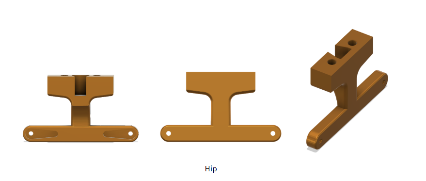
There are two Hip components of MicroFobo which are identical. The first component is placed in the front where it screws on to the two servos on the top joining the right and left leg. The second hip component goes behind Fobo where it hugs the band and keeps the upper section secure. The hip serves two important contributions to the design. Starting from the top, its flat edge is used to hold the housing of Fobo with the help of two screws on each hip. The two hips allow for the weight of the housing and all the components to be distributed appropriately. The second purpose of the hip component is to hug the higher section of fobo together and allow the legs to make lateral movements.
The Servo Wrap of MicroFobo attaches to the back of the hip servos. The wrap has a hole so it can be attached to the rear hip component of Fobo. This component also attaches to the servo band to ensure the hip stays secure. The design of the servo wrap allows Fobo to have higher degrees of movement by at least 45 degrees more.
The Servo Band of MicroFobo are four identical components in the design of MicroFobo. Each component holds two servos. The dimensions of this component are designed so the servos are held tightly in place to ensure the only movement is at the gear. The cutouts inside the square shape of the band make it so the servos can only go in a certain way and can be secured snug.
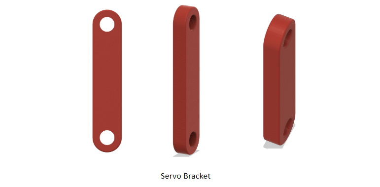
The Servo Bracket of MicroFobo is the component in charge of connecting the servos located at the top and bottom servo bands. The servo gears are meant to fit into the holes presented in the figure above. The top and bottom holes help with MicroFobos walking motion in two ways. With respect to the top hole, it is meant to help MicroFobo move its leg forward and back during the walking sequence. The bottom hole allows MicroFobo to move its ankle up or down. The ability to have vertical mobility will help MicroFobo adjust its walking sequence depending on the various terrains it may encounter.
The Foot of MicroFobo is two shoes like designs located at the bottom of MicroFobo. This component is meant to mount on the bottom-most servos. The way the foot is mounted on its servo allows MicroFobo to move the foot side to side as if it had an ankle. Ankle mobility helps MicroFobo avoid dragging its foot when walking. The small flaps on the side of the foot were designed to help MicroFobo distribute the weight it has above. Comparing this foot to previous generations of MicroFobo, the length of the foot was increased. The length was increased so we could be able to mount our batteries on the inside of the foot.
Verification & Validation Test Plan
This matrix provides complete traceability of every requirement. Specifically, every requirement is mapped to its description, success criteria, V&V testing designation and method, and Test Case(s) where the requirement will be tested. Note that some overlap between Test Cases’ requirements V&V is okay.
| Requirement Number | Requirement Text | Verification Success Criteria | Verification Method | Test Case(s) |
| 1 | MicroFOBO is based on the Project BiPed FoBo robot. The MicroFobo project, like Fobo will use 8 servos. | Does the robot have exactly 8 servos? | Inspection | TC-03 |
| 2 | MicroFOBO shall be controlled by the user through the Arxrobot application control panel for a portion of the mission. | The user can select anyone of the direction on the control panel and the robot responds. | Demonstration | TC-02 |
| 3 | MicroFOBO shall incorporate operating modes that allow the user to intercept the movement of FOBO while in automatic mode. | The user can press a button while the robot is walking, and the robot will respond. | Test | TC-02 |
| 4 | MicroFOBO shall transition to a stable standing position when it is not being told to walk forward in manual mode. | When the user is no longer selecting a control, the robot will stop and stand. | Test | TC-02 |
| 5 | When the autonomous walking algorithm is employed MicroFOBO shall continue walking forward until it sees a plaque and then stops within 25 cm. | The robot keeps walking until a plaque is placed in front of it, then it stops | Demonstration | TC-02 |
| 6 | Plaques will be placed between 0.3 to 1 meter, from MicroFOBO’s initial position. | Are the plaques within 0.3 to 1 meter? | Inspection | TC-01 |
| 7 | The distance between any two plaques will be between 25 cm and 1 meter. | Are the plaques between 25 cm to 1 meter from each other? | Inspection | TC-01 |
| 8 | The plaque faces of the 2 closest plaques shall be rotated no less than 5 degrees and no more than 90 degrees from the reference plaque’s orientation. | Are the 2 closest plaques to the reference plaque within 5 to 90 degrees of the plaque face? | Inspection | TC-01 |
| 9 | While the autonomous walking algorithm is employed MicroFOBO shall execute a right turn after a plaque has been detected. | Does it execute a right turn after it detects a plaque? | Test | TC-02 |
| 10 | MicroFOBO shall be able to complete a turning sequence in less than 7 seconds: 30 degree +/- 2 degrees | Does it execute a right turn in under 7 seconds? | Test | TC-01 |
| 11 | MicroFOBO shall be able to complete a 360-degree scan of its surroundings by using the scanning unit in the head | Can the sensing unit spin a total of 360 degrees to perform the scan? | Test | TC-02 |
| 12 | The scanning unit shall be able to map surroundings by detecting a minimum of 4 out of 6 plaques. | The user can uniquely identify 4 plaques from the scan. | Demonstration | TC-02 |
| 13 | MicroFOBO should be able to implement a moonwalking motion. | The user can recognize a moonwalking motion. | Demonstration | TC-02 |
| 14 | This project shall be constrained to a cost of $450. | The budget is less than $450 | Analysis | TC-04 |
| 15 | This project shall be completed by May 14th, 2020. | The robot has completed the mission before May 14th, 2020 | Inspection | TC-04 |
| 16 | Firmware programs will be written using Arduino De Facto Standard. | The code is written on Arduino | Analysis | TC-04 |
| 17 | MicroFOBO shall incorporate the 3DoT v9.05 or v9.1 | The user can identify that the 3DoT board is v9.05 or v9.1 | Inspection | TC-04 |
| 18 | MicroFOBO shall contain one custom-designed 3DoT shields. | The user can verify that the shield is custom. | Inspection | TC-03 |
| 19 | MicroFOBO shall weigh less than 1000 grams | The user can verify that the robot is less than weight limit | Analysis | TC-04 |
| 20 | MicroFOBO shall be controlled via Bluetooth 4.0 in compliance with the Bluetooth Special Interest Group (SIG) Standard. | The user can control the robot through the ArxRobot app | Demonstration | TC-02 |
Concluding Thoughts and Future Work
There are a few things our team has learned from working on this project. Generation 5, these are things you should keep in mind if you intend to improve our project.
As you can see on our final project video, microFOBO is now walking for the first time since the project was introduced in generation 1, though the walking actions are still choppy at best. If you are using a 3DoT board like we did then you will likely face some difficulty with updating the action frames. So prepare to spend a longer time than you suspect tinkering to get the walking sound.
Secondly, the new mechanical design will allow the weight to be distributed lower on the robot’s body which will likely aid your project’s mobility. If it becomes apparent that FOBO is too top-heavy, do what you can to keep some mass closer to the ground.
References/Resources
These are the starting resource files for the next generation of robots. All documentation shall be uploaded, linked to, and archived in to the Arxterra Google Drive. The “Resource” section includes links to the following material.
- Project Video YouTube
- PDR
- Google Drive see for Verification and Validation Plan


