Softform FuzzyBear
Summary Blog Post
Author/s: Arnel Cunanan, Jaime Cortez, Joshua Hurst, Gregory Marks
Table of Contents
Program and Project Objectives
Program Objectives
The Robot Company (TRC) will be debuting its 2020 line-up of toy robots and associated games at the Toy-Invasion 2020 convention in Long Beach CA over the week of May 11, 2019. TRC’s assignment is to make the 3D printed prototype to be showcased at the convention, prior to production starting in the second quarter of 2020. The robot that will be showcased is none other than FuzzyBear. FuzzyBear will feature our new ArxRobot smart phone application and the Arxterra internet applications (control panel) allowing children to interact and play games with FuzzyBear. In addition, the robots should be able operate autonomously in game mode. See game(s) (i.e, mission objectives) assigned to your robot by the Game Division. To decrease electronics cost, interoperability between all TRC robots will be maintained by incorporation of the 3DoT board, developed by our Electronics R&D Section. Modification of downloadable content is limited to software switch setting and robot unique graphics of the smart phone and Arxterra applications. FuzzyBear will be able to perform action specific commands using the Arxterra application. Modifications of electronics is limited to custom 3DoT shield and servo PCB as required by the unique project objectives of FuzzyBear. The Marketing Division has set our target demographic as children between the ages of 3 and 13, with a median (target) age of 11. To decrease production costs, Fuzzybear will be as small as possible, but still be big enough to give warm hugs. As with all our products, all safety, environmental, and other applicable standards shall be met. Remember, all children, including the disabled are our most important stakeholders. Our Manufacturing Division has also asked me to remind you that Manufacturability and Repairability best practices must be followed.
Project Objectives
Fuzzy bear is a animatoric softform teddy bear intended for children ages 3 and above. FuzzyBear will be temperature regulated to make sure it can give cozy hugs and a comforting experience to its owner. Animated motion of the bear, controlled from the ArxRobot App, includes walking, sitting, and wavings. The form factor of the fuzzy bear will be that of a “classic” teddy bear. The bear is part of our “adventure series” where the child can go on adventures with a provided (and/or purhased) story book.
Mission Profile
One cloudy afternoon, a child was taking a stroll through a forest and wandered down the wrong path. The child was cold, frightened and alone, not knowing the way back home. But have no fear, FuzzyBear is here! FuzzyBear, a prototype robot for any child that needs a friend, will reassure its owner that he/she is always warm and protected. FuzzyBear will guide the child through the forest while searching for dangerous bees. FuzzyBear will pause and proceed to sit down, alerting the child that it has located bees. Then, FuzzyBear will move its front right paw back and forth to swat the bees out of the way. FuzzyBear will have successfully led its child to safety when all the bees are swatted away, and the child is back home.
Project Features
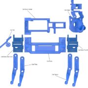
Included is an annotated diagram of FuzzyBear’s 3D model. FuzzyBear is a robotic-quadruped bear. The FuzzyBear team will be using a soft form cat as a reference structure and modifying it to be able to work in a fuzzy bear skin. A temperature regulating system will also be included within the fuzzy bear skin to prevent the electronics from overheating. Children will be able to operate FuzzyBear through the Arxterra App by direct control or autonomous mode. FuzzyBear will traverse the path using by means of object detection to detect objects, “bees.”
- FuzzyBear chassis will have 8 MG90 servos operating the 4 legs
- FuzzyBear chassis will have 3 SG90 servos operating the tail, neck and head
- The Cat body will be holding the 3Dot Board and corresponding servo shield
- Servos will be connected to the pins of the 3Dot board and Servo shield
- Each leg will have a MG90 serving as a joint that connects the femur and the tibia
- Each leg will have a MG90 serving as a joint that connects the tibia and the main body
- An external power supply will be located at the bottom of the cat body
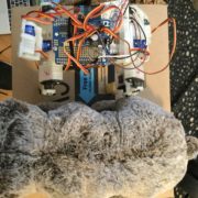
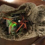
- FuzzyBear chassis will be inside a fuzzy teddy bear skin pictured in Figure 2
- FuzzyBear will use a peltier and heating clock to warm the bear in its fuzzy skin
- FuzzyBear will use the Adafruit VL6180 TOF with I2C interface to detect objects
- FuzzyBear will be controlled autonomously and be Arxterra application control
Requirements
Requirements will consist of Project Level 1 Functional Requirements (L1) and System/Subsystem/Specifications Level 2 Requirements (L2). The requirements should be quantitative, verifiable, and realizable. Due to Covid-19 epidemic the L2 requirements were not considered in the design review for FuzzyBear. A verification and validation test plan will allow for complete traceability of all the requirements.
Engineering Standards and Constraints
Applicable Engineering Standards
- IEEE 29148-2018 – ISO/IEC/IEEE Approved Draft International Standard – Systems and Software Engineering — Life Cycle Processes –Requirements Engineering
- Electrical Safety The National Institute of Occupational Safety and Health (NIOSH)
Environmental, Health, and Safety (EH&S) Standards
- CSULB College of Engineering (COE) Safety Resources — General Safety Information — Electrical Safety, Chemical Inventory — Electrical Engineering — CSULB Hazardous Material Inventory — Lead Solder
- IEEE National Electrical Safety Code (NESC)
- NCEES Fundamental Handbook (FE) Reference Handbook
- ASTM F963-17 The Standard Safety and Consumer Specification for Toy Safety
Project Level 1 Functional Requirements
The Project unique Level 1 Functional Requirements provide four test cases of basic, mission operation, assembly and disassembly, and logistics.
L1-1: FuzzyBear shall navigate autonomously (back-off use of App) from page 1 to “the end” of the story in 25 minutes.
L1-2: FuzzyBear’s chassis will be 3D printed using Nylon
L1-3: FuzzyBear chassis will fit in a normal sized teddy bear
L1-4: FuzzyBear should be warm to touch at a temperature of around 85 degrees at the belly of the bear
L1-5: FuzzyBear shall walk forward using the ArxRobot App
L1-6: FuzzyBear shall turn using the ArxRobot App
L1-7: FuzzyBear shall sit and wave its right paw to swat for each bee encountered
L1-8: FuzzyBear will have 4 limbs
L1-9: FuzzyBear shall detect bees
L1-10: FuzzyBear shall use a custom SMD PCB to meet project and mission requirements not supported by the 3DoT board. 11 Servo + Thermal Support.
L1-11: FuzzyBear will be powered with the 3Dot Battery and External power source
L1-12: FuzzyBear will communicate with the ArxRobot App via Bluetooth
L1-13: FuzzyBear shall take 20 minutes for assembly and disassembly. This will include avoiding dangling/exposed wires.
L1-14: FuzzyBear will/shall cost within our budget of $350
L1-15: FuzzyBear shall be completed by May 11, 2020
Allocated Requirements / System Resource Reports
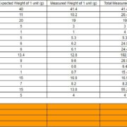
The mass allocation tabulates the expected weight from each resources. An allocated weight is given based on what FuzzyBear can support. We found the margin and uncertainty of each resource. The total of each value is located at the bottom. Using the totals and allocated weight, we find our contingency. Our expected weight values were not to far off from our actual measured weights. An digital scale was used to measure all the weights.
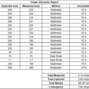
The power allocation tabulates the expected current drawn from each resource consuming power for the FuzzyBear robot. There a total of 11 servos, 3Dot board, servo shield, TOF distance sensor, fan, and peltier heating block consuming power. We compare the estimated current drawn with the actual current drawn. We also calculated the uncertainty and margin for each resource. The total of each value is located at the bottom. The totals include total expected current, total margins, project allocation, and contingency. A digital multimeter was used to measure all current draws. We initially had a wrong setup to measure the current draws. However, Covid-19 prevented us from retaking the measurements with the correct setup.
Project Report
The project report details the planning of the overall project. The project is divided up among the separate divisions which include Project Manager, Electrical Engineer, Mechanical Engineer, and Thermal Engineer. The Project Manager also shares duties with the Mission, Systems, and Tests division. The project planning will include some sections where our original project schedule might have altered in response to Covid-19.
Project WBS and PBS
As a result of the Covid-19 epidemic, the team was no longer able to meet in person to work on the project. As a result, teams had to figure out a plan of action moving forward, despite the situation everyone was. Each team needed to recreate a recovery plan that would detail what each team would be responsible for. Our biggest obstacle was not being able to meet to work on a single robot. Our solution was for the member who had the robot at the time of social distancing became in charge of hardware integration. A new schedule, shown below, was created to outline what goals we needed to meet. Each person has designated specific tasks or blog posts such as selecting bear skin, research on object detection, PCB design and soldering, Arxterra App, and thermal tests. Every person’s task would then be sent over to our hardware integrator for implementation with the robot. Zoom/virtual meetings were planned in preparation for each project meeting. Every meeting updates on tasks from above were brought up to address any issues. Discussed any problems, solutions, and questions that needed to be addressed at Project meetings with Hill.
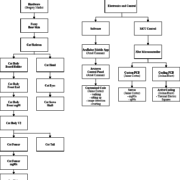
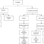
Product Breakdown Structure (PBS) is a hierarchical diagram that represents the breakdown of a product from a program or project.
As a result of Covid-19, we needed to create a more defined PBS for FuzzyBear. Tasks were divided up based on specializations. The main difference is the person who had the robot last became in charge of all hardware integration. Our members would work on their own specific tasks and send all gathered work and parts to the main hardware integrator.
As we can see, the product breakdown structure became more specialized and members in charge of specific tasks were changed. This updated PBS is not based on the semester as a whole but is based on what members were in charge of during Covid-19.
Cost
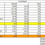
FuzzyBear was allocated a budget of $350. The cost of FuzzyBear prototype and research was in consideration of who the target audience was. Children ages 3-13 would need an inexpensive toy to keep them entertained. The goal is build FuzzyBear at a low cost, so we can implement cheaper parts in future versions. Budget list includes the total part list for FuzzyBear chassis, all hardware was included, PCB, fuzzy skin, and thermal parts. Instruments used to test was also not included because they were either already owned or provided by the school. Our expected total cost of parts ended up matching our allocated budget.
Schedule
Schedule (Pre-Covid 19)
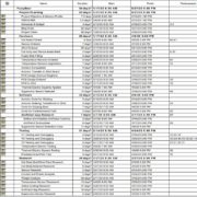
The FuzzyBear schedule is shown below and serves as a guideline for the production of FuzzyBear. The schedule is divided into project planning, hardware, software, testing, and research. Project Libre was used to create the schedule.
Schedule (During Covid 19)
Project planning needed to be updated as a result of Covid-19. The above schedule tabulates what the schedule would have been if there was no epidemic. The schedule below tabulates what tasks needed to be performed to continue the project. Figure 10 shows what was worked on at the beginning of the stay at home order established by the Californian government to the end of the semester.
Critical Path
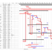
The critical path is shown next to the schedule to show the order of objectives to be completed. Project Libre was used to create the critical path. The path shows what was critical to creating FuzzyBear.
Burndown and/or Percent Complete
In the combined Project Design Review created by all the Project Managers and Professor Hill, the burndown was removed. Covid-19 affected the completion times of certain aspects of a project because there was a gap while figureing out how to more forward with how the class was going to be performed.
Concept and Preliminary Design
This section highlights the resources required to complete the FuzzyBear project. It shows the many tasks that were performed leading up to the final version of FuzzyBear. The research will also include where the idea of FuzzyBear came from.
Literature Review
OpenCat – The first literature is where the idea of FuzzyBear started. FuzzyBear chassis is based on the OpenCat chassis. All information and STL files relating to starting your own FuzzyBear project can be found here.
Torque Analysis – A torque analysis was required because FuzzyBear had trouble standing on its own weight. We had to do power tests and torque tests to figure out what the problem was.
Object Detection – A trade-off study was performed to select the best method for detecting the “bees” in FuzzyBear’s path.
Thermal Study – A thermal study involving multiple tests were performed to determine if heating or cooling was needed. Temperature tests allowed us to determine if FuzzyBear can be safe for a child to use.
PCB Design – FuzzyBear required more servo pins in order to operate. A servo PCB was designed with multiple iterations.
Firmware Design – Project code is included. Also, it discusses how to issue the commands specific to FuzzyBear.
Design Innovation
The most creative solutions that this generation created was object detection, thermal application, and soft-form skin. As this is FuzzyBear’s generation, a lot of innovation was based on what we can add to the chassis.
For object detection, a trade-off study was performed to determine which form of object detection FuzzyBear will use. Some tests were performed to aid in our selection. The trade-off study is located in Literature Review. The test can be found below.
Thermal application was also new to FuzzyBear. Heating of the bear required a lot of tests. Various ideas were proposed because there were various circumstances that needed to be addressed. Heating the bear required specific parts to be purchased and tested. The tests would allow us to decide what was the best way we could heat up FuzzyBear when it is in its softform skin.
Conceptual Design / Proposed Solution
FuzzyBear chassis is shown below. The design of the parts were assembled and implemented for our design innovation. One problem we ran into was that FuzzyBear was able to fit in the Softform teddy bear, but was unable to move because skin was really tight on the shoulders. The idea was alter the cat body about 4 mm for the chassis to fir inside the skin.
FuzzyBear is able to fit in its softform skin. However, without access to a 3-D printer we were unable to make physical adjustments to the chassis. Instead the chassis will be presented. Regulating the temperature of FuzzyBear will be performed outside of the skin using a fan and peltier heating block.
In addition to heating, we had the problem of not having enough servo pins on the 3Dot board. To address the problem, our solution was to create our very own servo PCB that would allow us to attach all our servos and our object detection device.
System Design / Final Design and Results
System Block Diagram
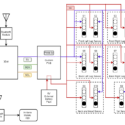
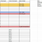
As we can see from the diagram, we have a total of 11 servos connected to our design of the custom servo PCB. Each servo has 2 wires. One wire is supplying a 5V unregulated supply. The other wire is ground. The servo PCB will be placed on the 3Dot board. The Arxterra Mobile Application will able to communicate with the 3Dot board via bluetooth communication. The specific pin layout will be located in .the interface matrix
Interface Definition
Modeling/Experimental Results
Below are the links to modeling and our experimental results
- Thermal Test
- The link showcases how thermal research was performed.
- The 3 tests performed to determine temperature of the bear.
- Implementation of thermal design.
- Torque Analysis
- Talks about torque issue for V1.
- Torque analysis proves rated torque of the servos are consistent with the torque at each joint.
- Quadruped Walking
- Study of what quadruped walking is and how it can be applied to the robot
- Servo Trade-Off Study
- Details study of different servos
- Selection of servos
- Object Detection Trade-Off Study
- Comparison of different forms of object detection
- Selection and narrowing our options.
- Object detection test was performed to meet our detection requirement
Mission Command and Control
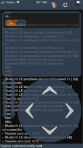
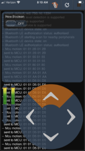
To allow the user to be in more control of fuzzy-bear the decision was made to have the move command be joysticks. the joysticks were mapped to different movements of fuzzy-bear such as when having the forward arrow pressed fuzzy-bear would initiate the the code for the forward walking. The joysticks are continuously updating the direction so the user can change the arrow that they are pressing and an updated will be sent to the 3-dot board resulting in fuzzy-bear executing a different movement. Below is the Arxterra user interface when the forward button is pressed to start making fuzzy bear move forward.
Electronic Design
The electronic design of consisted of a Servo PCB with multiple iterations. Bread boarding, EagleCad, and production of the PCB itself lead to the complettion of our electronic design.
PCB Design
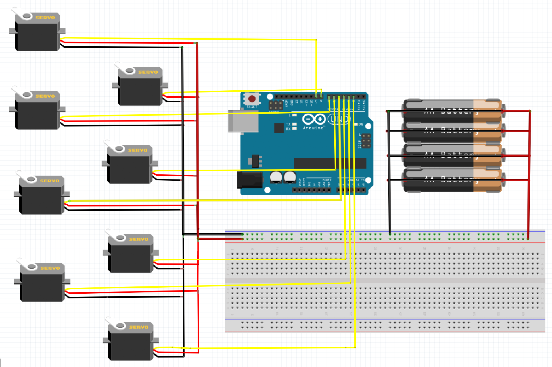
For the first prototype, Fuzzy Bear had a breadboard on its back and was powered through the Arduino Uno 5V pin. The circuit looked as shown below in the Fritzing diagram without the external battery pack. This prototype was prone to failure as Fuzzy Bear struggled to lift its own weight but it did however succeed in executing movement commands. Why didn’t this work? Considering that when the Arduino Uno is powered via USB cable, each pin can only output about 40 milliamps and the servos need several hundred milliamps to get Fuzzy Bear on its feet. This leads to the addition of the external battery supply as shown in the Fritzing diagram. With the battery pack, we were able to verify that the Arduino did in fact lack a lot of power. This new improvement led to the verification of the MG90 servos being strong enough to get Fuzzy Bear through a day’s worth of work.
For the first iteration, we initialized the board dimensions and placed the header pins in the correct position to make it compatible with the 3dot board. From the schematic, we can see that this version contains the jumpers, PCA9685 IC, reverse voltage protection IC, an optional capacitor, and most importantly the pinouts for the servos. This design seemed perfect for Fuzzy Bear to power up all its legs but one major flaw came out of this design. The 3dot board has a battery that takes up a decent amount of space in addition to the towering height it obtains. This is an issue due to the fact that the PCB is going to be stacked on top and therefore won’t have enough height clearance between the board and the battery. The design had to be updated.
Other remarks that Professor Hill had mentioned were regarding the trace cursor size, the surface mount components size, and the resistor values that are in series with the LEDs. The cursor size is at a default 6 which is fine for most PCB manufacturing standards but this also leads to an increase in a defective PCB. Therefore the size needs to be at least 10 to be certain that this does not happen except for the power traces which need to be larger for more current to flow through. The SMT component size that Adafruit used were 805s but for convenience, 603s were recommended instead. As for the resistor value, it changed from 330 ohms to 1000 ohms to make it more power efficient. All of these corrections need to be considered in the 2nd design as we will show next.
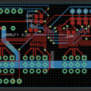
In the 2nd iteration, the first major change we can see is the battery cut out. Thanks to Sojourner from the previous year, Jaap was able to provide me with his team’s PCB dimensions with the verified cut out for the battery. The design from the 1st iteration required removing some unnecessary pins and components to get all of it to fit within these dimensions. This servo shield only needs 11 servos to function which is why we removed 4 pin servo connectors from the layout. Three of the jumpers that are needed to assign a unique address to the shield were also removed in the process since we’re only using two shields. As a result, the 2nd design is shown above that includes the adjustments of the issues mentioned previously.
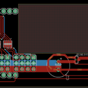
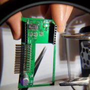
Engineering is performed to better the already improved design which is why the 2nd iteration needs to be improved to give Fuzzy Bear its money’s worth. As mentioned by Chris, this design isn’t fully utilizing the ground planes to make it feasible to connect all the ground traces together without using the actual wire trace. This will clean up our design and free up space for future adjustments if needed. The 2nd design also creates some interference issues when connecting the servo wires to the pins once it’s time to stack the thermal shield. Professor Hill brought up the idea of moving the servo pins out onto the edge next to the battery to make the overall design more convenient. This allows the connections to be made without having to take off the thermal shield each time. The final iteration design takes all of this into consideration and is shown below.
Firmware
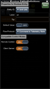
In the first part of the code we are initializing global variables that are going to be used as well as including libraries, And assigning subroutine names to a hexadecimal number that ill be sent by the transmitter by user input, these subroutine names will be mapped to different subroutines. In our code there are 8 subroutines label subroutine1 to subroutine8 and the are mapped to the subroutine names servomove1 to servomove8, and these names are mapped to the hexadecimal number 0x42 to 0x49. In subroutine 1 we have the code for the bear to sit and move its paw up and down three times to swat away three bees. If we were allowed more time, we would have used all the subroutines created and incorporated more movements for fuzzy bear. We did override the move command these was in the move handler subroutine when the user is using the ArxRobot Application the user can use joysticks buttons to control the movement of Fuzzy Bear. When the up Arrow is pressed it will change the parameters to 0x01 and 0x01 which will run the first if statement in that subroutine and the code for forward movement is there. The left joystick will make fuzzy bear turn left and the right joystick will make fuzzy bear turn right and the back-joystick button will make fuzzy bear sit and wave three times. At the bottom of the code we have the different loops for the commands that Fuzzy bear will need to have to be able to move and these codes will be called on when the bear needs to move in a certain direction.
Mechanical/Hardware Design
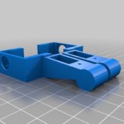
Above are the SolidWorks generated 3D Models in an annotated diagram. Looking closer, you can see there are 4 femur and 4 tibia. Below I will show how these parts come in pairs when being printed.
The actual parts can be seen in the following image, The parts are already assembled but is in a similar orientation as the diagram in Figure 21.
Verification & Validation Test Plan
TC-01: Basic Operation
Demonstration of the ArxRobot App will be performed. Demonstration will consist of servo control of the FuzzyBear through Bluetooth commands. Thermal demonstration will prove FuzzyBear is being heated.
TC-02: Mission Operation
FuzzyBear will travers a predetermined path by walking. When FuzzyBear come across a turn in the path, FuzzyBear will walk and face the direction of the turn. FuzzyBear will detect a total of 3 bees in the path and sit and wave signal the swatting of the bees. Mission will conclude when FuzzyBear reaches the end of the path.
TC-03: Assembly/Dissassembly
Visual requirements will be included in this section. Assembly and disassembly of FuzzyBear will be performed. The material of the chassis and the skin of FuzzyBear will be included here. A mass test will be shown.
TC-04: Logistics
Test cases included are based on constraints and target dates.
Concluding Thoughts and Future Work
Some of the problems that we have face were the STL files from OpenCat. The files are fixed and cannot be edited. Also, the STL files can’t be consolidated in SolidWorks. However, we found out at a later date that the files can be consolidated in Fusion 360. Fusion 360 allows the files to be consolidated, but can’t edit each piece to adjust alter it in your desired preference.
Probably the most important thing a future group should look into is selecting the softform teddy bear skin. Since the project relies on fitting the FuzzyBear chassis within the skin, it is important to search for a skin. Doing so will give the team ample time to create new STL files that would match the structure of the softform skin. Deciding on the skin late led to not enough time to produce a new STL file for the final version.
Although Zoom meetings were used specifically because of the epidemic, we still believe it serves as a useful tool when updating other group members with problems and solutions about the project. This experiment with virtual learning proved that it is still possible to work on a project without in-person meetings.
References/Resources
These are the starting resource files for the next generation of robots. All documentation shall be uploaded, linked to, and archived in to the Arxterra Google Drive. The “Resource” section includes links to the following material.
- Project Video YouTube or Vimeo link (see samples linked to here)
- Design Review
- Project Libre
- Verification and Validation Test Plan
- SolidWorks Files
- Link to Code Blogpost
- Link to PCB Design
- Link to Costs
- Project Video

