Sojourner Spring 2020
Commutator Noise Initial Study
Author: Robert Pearson
Verification: Robert Pearson
Approval: Chris Hirunthanakorn
Table of Contents
Commutator Noise
Some of the risks for this method are if the motor is running constantly, especially for an advanced braking system, a capacitor is usually run across the motor to reduce noise and prevent spikes in the voltage. The spikes can reduce the lifespan of the motor, the sojourner uses fairly small motors so this affect on the motor is fairly small. This would be a bigger issue if we had bigger motors, but even with small motors we still need to consider it.
There are two methods to measure these commutator spikes, Ripple Counting and Transient Counting. Both of these methods require knowledge of the number of poles the motor has. Ripple Counting can be done through measuring fluctuation in the current, which is proportional to the magnetic field according to Lenz’s law. Ripple counting is better for a lower number of coils because the ripple has a much stronger effect. Motor speed, temperature, torque, and orientation are all factors for finding these spikes which can make it harder to determine which spikes are due to the external factors creating the excess noise.
Transient Counting can be found all throughout the power supply wire, which means there is no need for a resistor in series to measure the current which Ripple Counting requires. When the commutator loses contact to the brush there is a voltage spike. The two types of transients are Kick Back Transient and Impedance Transient. For Kick Back Transient the waveform is periodic if the rpm is stable, so one should be able to determine where the brush engages and disengages with the commutator by observing the voltage. Impedance Transient views the spikes due to the sudden change in impedance when the brush engages and disengages.
Background
Commutator noise can control speed by looking at spectral components. This method is dependent on a higher amount of inductor coils. Current spectral components are easier to examine due to a larger amplitude in comparison to the DC voltage component. The spectral current can be calculate by (Vcc-Vm)/Rs. Vcc is the ideal voltage source, Vm is the voltage of the motor and Rs is the resistance. Another notion to consider is that to calculate a way to efficiently translate voltage spikes into RPM data is through commutator poles, and at this time Polulu does not document the number of poles in the Micro Gear line of motors.
There are some risks posed when using commutator noise to measure sensor less encoding. The commutator noise effect is best seen when no diode is used in a circuit to limit voltage spikes. Running the motor with the noise created could possibly shorten the Micro Gear Motor’s lifespan.
When looking for a sensorless encoding circuit, we looked for a circuit that would be applicable for a Brushed DC motor. A brushed motor holds a set of magnets. These magnets are of opposite polarity so they are naturally attracted to each other, when powered the motor’s armature is rotated by the magnet’s draw toward each other.
Initial Testing
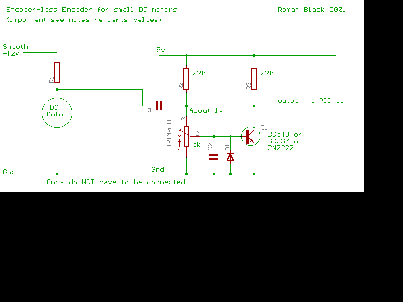
During our research, we came across a design for sensorless encoding in regards to commutator noise that belongs to Roman Black.
Figure 1. “Encoder-less Encoder for Small DC Motors” – Designed and Owned by Roman Black
Roman Black’s circuit was chosen due to the simplicity and availability of parts for initial testing. Further circuits we will discuss require specific SMD components. Roman Black’s circuit also requires no code, thus making it easier to breadboard and grab quick results. Although for our circuit, some adjustments were made.
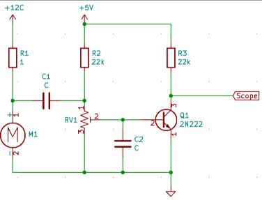
Figure 2. Commutator Noise Adapted Circuit Schematic
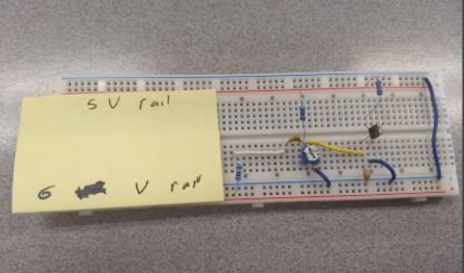
Below is the commutator noise circuit we built for initial testing. In this circuit, R1 scales the ripple voltage and current sensing with a tradeoff for a lackluster motor performance. C1 allows a pulse (on/off) to be passed through the circuit. C2 assists in smoothing the ripple voltage. For our circuit since Roman Black’s circuit was designed for larger motors, we had to experiment to find proper values that show results (voltage spikes). We adapted this circuit for use with Micro Gear motors, so we removed the Diode from the original design, as the diode is meant for use of motors that use 2 Amps or more.
Figure 3. Bread Board Commutator Noise Circuit Schematic
Our results are displayed below. For this setup we used a value of 10K for Resistor 1, C1 had a value of 3.3uF while C2 had a value of 9pF.
Depending on the duty cycle, we can see the voltage is periodic with its spikes. The voltage peaks when we see that a rotation of the Micro Gear Motor occurs. The voltage spike is dependent on speed, so the higher the peak the greater the speed. This data can be used further into a value for an ADC converter to use. From this we can calculate rpm of our motors.
Figure 4. Oscilloscope Results
Ripple Counting Circuit
As we continued our testing of the Commutator Noise Sensorless Encoding method, one thing that we wanted to test would be the ability to control the speed of the motor more efficiently. This method of control would be good for testing our commutator noise circuit with an Arduino Micro controller.
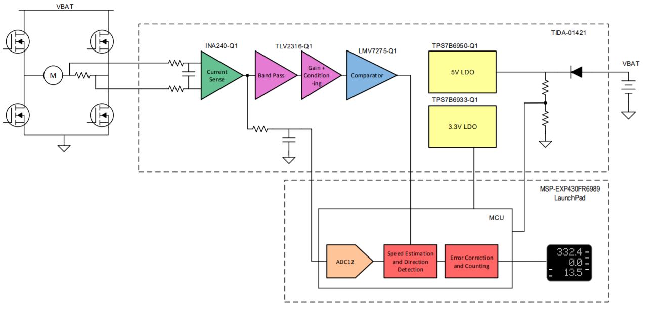
To experiment with the viability of the Commutator Noise Sensorless Encoding method, we decided to test a PCB designed by Texas Instruments. We decided to change pace as this circuit could possibly reduce the time we spent in the testing phase of our project. The Texas Instrument’s TIDA-01421 was designed to work with DC Motors that are implemented on retaining memory on distance such as windows, sliding doors and gates. The only downside to testing this circuit is the cost and lead-time on construction. The circuit must be designed to work with a PCB due to parts such as the INA240-Q1 Current Sense Amplifier being only available as SMD components. The TIDA-01421 is able to take in a current and measure it. From this step the signal is then filtered and converted as a 3.3V square wave logic output for a processor to count the position of the motor. Counting of motor’s position can then be adapted to counting the rpm. Figure 5 references these steps through a block diagram.
Figure 5 TIDA-01421 Block Diagram, Property of Texas Instruments
Texas Instrument’s TIDA-01421 begins by measuring the motor current that can be found by (Armature Voltage – Back EMF Voltage)/ Armature Resistance. The current sense amplifier can be used for bi-directional current sensing through the use of the full-bridge rectifier. The output of the current sense amplifier is sent to the Band-Pass Filter stage. The filter takes into account the ripple and is able to measure the frequency which can then be relayed into rpm data for the ADC converter to handle. The band-pass filter then removes any extraneous noise from the signal and gives it to a differential amplifier. The differential amplifier then gives the clean signal from a range of 0v – 3.3 v for the comparator to use.
Further design and testing of the TIDA-01421 can be found here.
Conclusion
The commutator noise, if setup properly, can provide accurate data through the ripple counting method. This method is applicable for Sojourner’s Brushed DC micro motors, and will be further expanded upon using the design from Texas Instruments.
References
“Using DC Motor Commutation Spikes To Measure Motor Speed RPM.” Precision Microdrives, Precision Microdrives, 2AD, www.precisionmicrodrives.com/content/using-dc-motor-commutation-spikes-to-measure-motor-speed-rpm/.
Vasquez-Sanchez, Ernesto, and Joseph Sottile. “A Novel Method for Sensorless Speed Detection of Brushed DC Motors.” Applied Sciences, 24 Dec. 2016.
Nottelmann, Jan B. “Sensor‐Less Rotation Counting in Brush Commutated DC Motors.” IdeAdvance, 2011.
Acaban, Aldrin, and Maria Canada. “Sensorless Position Control of Brushed DC Motor Using Ripple Counting Technique.” Microchip, 2019.
Black, Roman. “DC Motor Speed Encoder.” www.RomanBlack.com, April 2001. https://www.romanblack.com/encoder.htm
https://www.ti.com/tool/TIDA-01421
www.electrical4u.com


