Spring 2016 RoFi: Soldering Servo Driver
Christopher Andelin (Project Manager)
Mario Ramirez (Systems Engineer)
Qui Du (Manufacturing Engineer)
Andrew Laqui (Electronics and Controls Engineer)
Henry Ruff (Electronics and Controls Engineer)
Soldering Servo Driver
Qui Du (Manufacturing Engineering)
Due to the transition from the Arduino Mega to the Arduino Uno it is necessary that we implementh the servo driver to provide the pins we need. Below are the steps I used in soldering our header pins to our 16 channel servo.
Tools
- Solder
- Soldering Iron Cleaner
- Soldering Station
- Soldering Iron
- Unsolder Pump

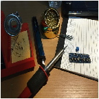
Image 1: Soldering Tools
Servo Driver soldering process
- Turn on the soldering station and wait for the soldering iron to reach the desired temperature
- Clean the servo driver and header pins
- Install the header pins into the servo driver
- Heat the connection of the pin and the driver with the tip of the soldering iron for a few seconds, and then apply the solder at the connection
- Allow the solder to cool
Note: Only apply heat to the connection; do not apply heat to the solder.

Image 2: Servo Driver
Soldering Completed:

Image 3: Final Product
Source
https://learn.adafruit.com/downloads/pdf/16-channel-pwm-servo-driver.pdf.