IloMilo / Spring 2020
Flight to Orbit – Designing with SolidWorks (Tutorials and More)
Author: Farland Nguyen
Table of Contents
Introduction
Even before the increasing accessibility to 3D printing causing the expediting of rapid prototyping, 3D solid modeling computer-aided design (CAD) programs have always been relevant to engineering. Designs that used to require multiple 2D sketches to express a 3D object could now be completely designed as a single 3D object that could be interacted with. Not only that, these CAD programs were also able to simulate testing and real-world conditions without the commitment of building the object first. SolidWorks is one of these 3D CAD programs and is, arguably, the most widely used within the industry. Therefore, SolidWorks is fundamental to any Design and Manufacturing position and, most importantly, free to CSULB students. This blog post will lay out helpful tutorials and resources used in the creation of the IloMilo joystick from view of a SolidWorks novice, as well as focus on the tools and design options that SolidWorks provides.
Launch: Overarching Mindset
Solidworks is just a means to an end: the creation of an interactive, 3D model of a potential real-world object. Even though Solidworks drastically reduces the skill curve to physical designs, there is still a skill curve. Therefore, I highly recommend doing some prep work before actually tackling Solidworks. Doing some simple, rough sketches of the final object helps enormously. These will allow a user to obtain several different perspectives of the object and allow them to break down a complex design into several simpler ones. Therein lies a crucial, comprehensive aspect of Solidworks: complexity can always be simplified with the right perspective. Just because design appears complex as a 3D object doesn’t mean that putting it in a 2D perspective is as complex. A hollow sphere cut in half is appears as two circles, with one inside the other, that is revolved around a central axis line. By doing this, users can cut down on their load as they lean heavily upon the more straightforward tools of Solidworks rather than relying upon the complex functions that require a textbook to understand.
Powered Ascent: Tools of SolidWorks
SolidWorks has a multitude of tools and processes that create a three dimensional part as well as modify and fine tune parts to meet specific and changing requirements. Below is a link to a website created by Dassault Systemes, the owners of SolidWorks, that will be a helpful assistant to the following tutorials.
The most important aspect of SolidWorks, and often overlooked, is how to navigate in a three dimensional space. There are three major methods:
- Middle Mouse Button – To move the part around in the 3D space, click and hold the middle mouse button while the mouse is on the part. Moving the mouse with the middle mouse button held down will rotate the part on all three axes.
- Mouse Wheel – Scrolling the mouse wheel will zoom in and out on the area where the mouse is pointed at.
- Space Bar – Using the space bar will open the orientation menu that will move the part based on a pop-up orientation box superimposed over the part.
Maneuvering the part will require some time to adjust to the 3D space. Once this can be reasonably achieved, we will shift gears to the tools of SolidWorks. These tools, listed below, allow the part to not only be formed in the 3D space, but also be altered.
- Sketch – Opens a 2D plane where the actual drawing of the part occurs. Shapes and lines are offered as options for easier usage.
- Smart Dimension – When a side is selected, smart dimension will give the width, length, radius, or circumference, based on the type of shape selected. Selecting two separate sides will measure the length between them.
- Extrude Boss/Base – Select either a 2D sketch or certain aspects of multiple 2D sketches to protrude in any direction of the third dimension, creating a solid.
- Extruded Cut – Selecting a 2D sketch on top of a surface will remove all material in the shape of the sketch, cutting the original solid.
- Fillet/Chamfer – Creates either a rounded edge or cuts away the edge to create a slope
- Revolved Boss/Base – Select either a 2D sketch or certain aspects of multiple 2D sketches to rotate around an axis of the third dimension, creating a solid.
Staging: Designing a Part
The first step to creating a SolidWorks part doesn’t involve SolidWorks at all. Planning out the part, be it drawing out the part or even just visualizing the part, is crucial as SolidWorks is a blank canvas and not an area of inspiration. By doing this, you can more easily design, create, and modify a part in SolidWorks when given the knowledge of the tools and their possible constraints.
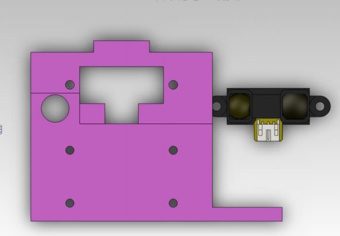
When designing the IloMilo joystick, I started from scratch with both my joystick design and my SolidWorks knowledge. Any pre-build designs for joysticks online were not able to meet the requirements for our bots and, therefore, I designed a preliminary joystick design that opens up the door for me to iterate and enhance the design in later versions. Once I had a vague idea of how I wanted my joystick to look, taking elements from other joysticks because creating without inspiration is hard, I used several tutorials to kick off my journey into SolidWorks. I was able to use the following tutorial to create a base on which I would build my knowledge and experience.
Once I was able to complete the tasks from this tutorial, I looked further into other tutorials. There are several video tutorials I found, displayed below, that are considerably more helpful as the tools of SolidWorks are explained with more depth and one can easily follow along as every action is able to be viewed rather than be told.
Figure 3. SolidWorks Parts Video Tutorial 1
Figure 4. SolidWorks Parts Video Tutorial 2
Figure 5. SolidWorks Parts Video Tutorial 3
Figure 6. SolidWorks Parts Video Tutorial 4
One thing that these tutorials doesn’t cover is why there is only one part per part file. While multiple parts can be created in a single part file, it is rather unwise to do this. When multiple parts are created in a part file, each part is locked into place on the original plane that it was drawn on and cannot be moved to either meet with other parts or flipped to different planes. This also makes it harder to shift the parts to correctly align them to maximize the efficiency of a 3D printer. If multiple parts are designed, an assembly file is where they can be put together to ensure that all the parts will actually fit as well as align them to best be 3D printed.
Upper Stage Burn: Assemblies and Beyond
To manipulate and combine multiple parts together, an assembly file is required. An assembly file will allow all the parts to be placed into their positions to visualize the final outcome. This is also where all the parts can be moved onto a single plane to allow them to be more easily 3D printed. The following tutorials were of great help to understanding how assembly files differentiate themselves from parts files as well as how they work.
Figure 8. SolidWorks Assembly Video Tutorial 1
Figure 9. SolidWorks Assembly Video Tutorial 2
Engine Cut-Off: Multiple Design Methods
While the previous tutorials are more than enough to cover what is required for basic design parts and assemblies, as well as some 3D printed applications, SolidWorks offers more than assembly and parts creation. If one has the time, here are several other resources that delve into the complexities of SolidWorks.
Figure 12. SolidWorks Video Tutorial Playlist 1
Figure 13. SolidWorks Video Tutorial Playlist 2
As with most programs, SolidWorks allows the user to achieve their desired result with multiple solutions. These tutorials should give the baseline for one to create their parts and assemblies by using the tools in creative ways based upon the users’ discretion. An example of this is creating a cube with a hole through its center: a square sketch can be drawn, protruded, then a circle sketch can be drawn on one of the faces and extruded. Or, a sketch of a square with a circle in the center can be drawn and protruded to achieve the same result. Due to this freedom, it is pertinent to keep track of the sketches, tools, and processes used to create a part, just in case modification is required later on.
In Orbit: Conclusion
These tutorials were some of the most useful in my understanding with Solidworks. There are a multitude of other tutorials that I would recommend to fit all types of learning styles. However, all of these tutorials are only here to create a baseline for this knowledge. Self-exploration of Solidworks will yield even greater results and understanding at the functions this program has.
Even with this knowledge, be prepared and willing to toil over a single design for days or weeks only to throw all your work away. Designs can only be forced up to a certain point before they become obsolete. Remember, Solidworks is nothing more than a tool. A well-designed and modular tool, but a tool nonetheless. Solidworks will not create the design for the user or guide the user to a design; that is left up to the user’s discretion. Every choice made will be made by the user and, therefore, every mistake will be made by the user. There will be host of reason why a design will not work and they can pop up at any time during the use of Solidworks. The user must make the decision if the design can be salvaged or not.
References/Resources
- https://www.grc.nasa.gov/WWW/K-12/rocket/Images/rktrflght.gif
- http://help.solidworks.com/2011/English/SolidWorks/sldworks/LegacyHelp/Sldworks/Overview/StartPage.htm
- http://web.csulb.edu/~hill/ee400d/Division%20Documents/Manufacturing%20Division/3D%20Modeling/Solidworks%20Tutorial%20-%20Part%20I.pdf
- https://www.youtube.com/watch?v=HKSo99hGDd4
- https://www.youtube.com/watch?v=cy3ExIAcI2Y
- https://www.youtube.com/watch?v=ll_9D6J2yT0
- https://www.youtube.com/watch?v=PovLu7Mnhgc
- http://web.csulb.edu/~hill/ee400d/Division%20Documents/Manufacturing%20Division/3D%20Modeling/Solidworks%20Tutorial%20-%20Part%20II.pdf
- https://www.youtube.com/watch?v=yGvZ3Jly1mI
- https://www.youtube.com/watch?v=IR4YsN2d39w
- https://static.sdcpublications.com/pdfsample/978-1-63057-148-1-3.pdf
- https://files.solidworks.com/pdf/introsw.pdf
- https://www.youtube.com/playlist?list=PLBQySgtN0yKOhuW0yw3r_AspZkF-8yS8x
- https://www.youtube.com/playlist?list=PL4mNbJmXLK0dn7wdGYOncwFRAQoFIgXiA


