Table of Contents
Objective
By Jessica Benitez
The objective of proximity sensing is to “detect the presence of objects within its vicinity without any physical contact” 1. In our case, Ilo uses a proximity sensing device to both detect an object and be able to distinguish them by using its height. The main purpose of utilizing the SparkFun VL6180 Time of Flight Sensor is to distinguish whether or not the object in front of it is Milo (the other robot) or an obstacle it must maneuver around to continue its search for Milo.
Hardware Design Process
The components used for this implementation are an SG90 servo, a paper bot using the 3DoT board, and a SparkFun VL6180 Time of Flight Sensor. Some of the key features of the Time of Flight sensor are that it has an absolute range from 10 cm up to 25 cm.
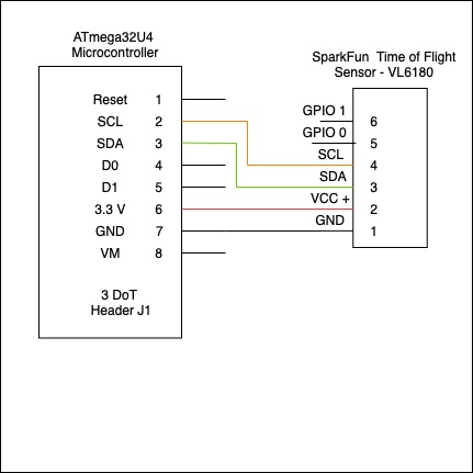
The following is a schematic of how to connect the SparkFun VL6180 Time of Flight Sensor:
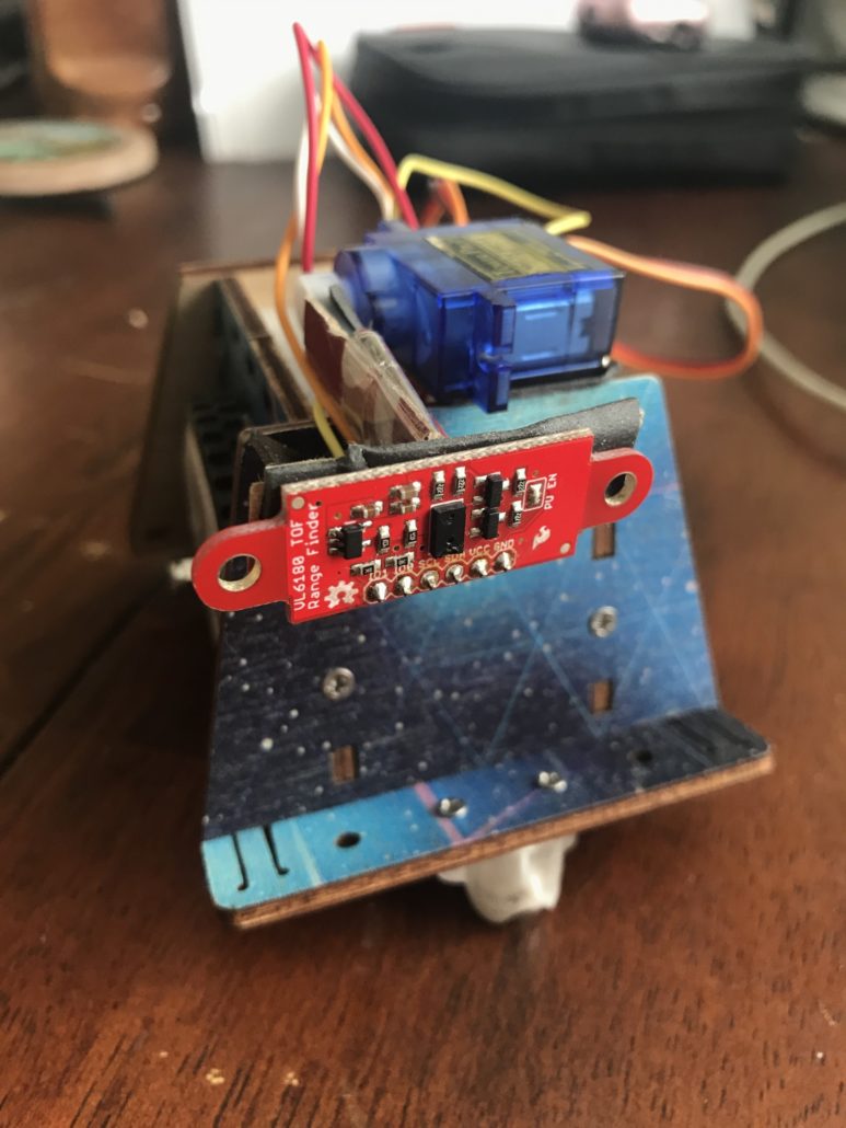
After wiring the Time of Flight sensor to the 3DoT board, it is attached to a servo which is situated to allow for vertical movement.
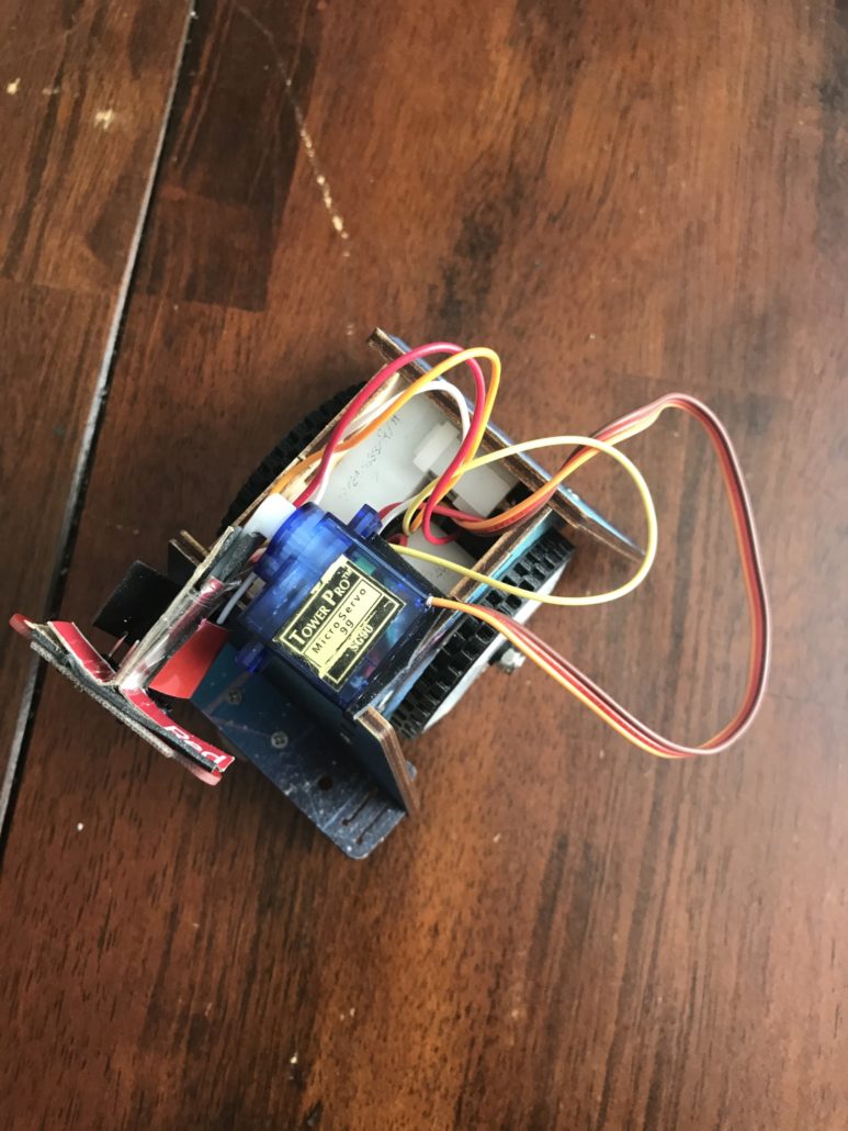
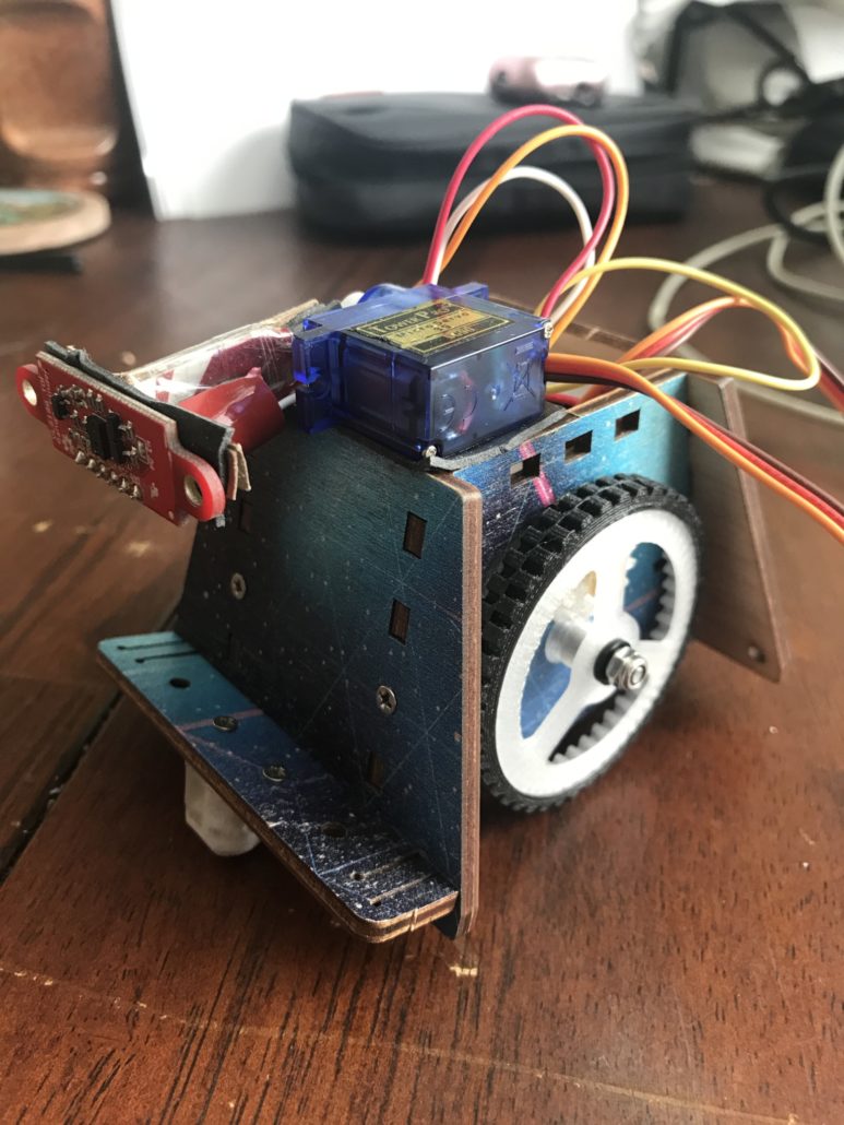
The gallery above demonstrates a fully assembled Paper Bot with sensor and servo.
Mathematical Concepts of Item Measurement
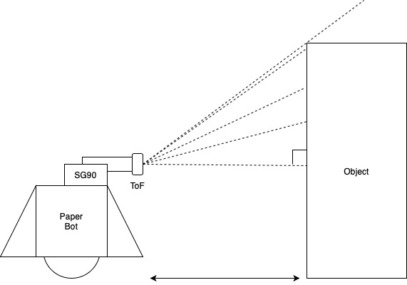
The robot is set automatically in the forward motion from the start, unless there is an object interrupting it. Once it approaches an object, it stops to take its measurement. Figure 2 represents an ideal situation where the object’s front side is parallel to the time of flight sensor.
In order to find out the measurement of the item, the time of flight sensor will use the servo to scan the item in front of it. The servo will begin at 0° which will serve as the defined base of the object. Due to circumstances involving the placement of the servo, the servo in the following code is initialized at 90°. The base sits at a fixed offset of 70 mm above the ground. Each object tested is over 70 mm to accommodate for this offset. All of this is taking place in the Measuring State (measState). In order to determine the height of the object, trigonometry basics are used for its calculations.
The measuring state begins by taking the first distance and placing it into variable named previous. The servo then begins to increment by 1 with a delay to allow for a proper reading. Each value taken is then stored in the variable named current. In order to ensure the time of flight is still reading the object, the difference between the current and previous is taken and should not exceed 100. As tested by SparkFun and I, the farthest the time of flight sensor can read is up to us 255 mm. Therefore, as soon as it reaches over the object, it reads 225 mm.
The next step is the calculation of the height of the object. Due to each object having the offset of 70 mm, we disregard it and take the measurement of the rest of the object. In the Arduino library, the math.h header includes mathematical computation. One thing to note is that the trigonometric functions utilize radians and not degrees. Thus, a conversion from degrees to radians is implemented. Using the figure above, it is important to note that the time of flight and the object create a 90° angle. This makes calculation simpler. The following equations were used to calculate the remaining height of the object.
Each objects height is calculated as Offset + Height = True Height ± 10 mm of uncertainty. As mentioned above that the code below initializes the position of the servo at 90°, the code includes a formula that takes the angle of the last measurement and subtracts 90 to get the correct angle measurement.
int measState(){
    stopPlease();
    // MOVE the servo
    for (pos = 90; pos <= 180; pos += 1) {
      delay(250); //orig 500
      current = sensor.getDistance();
      Serial.print("\nPrevious Distance (mm) = "); Serial.print(previous); Serial.print("     ");
      Serial.print("Current Distance (mm) = "); Serial.print(current); Serial.print("\n"); Serial.print(pos);
      //Serial.print("Distance measured (mm) = ");
      //Serial.println( sensor.getDistance() );

      if ((current - previous) < 100) {
        previous = current;
       }
      else {
        double angle = ((pos)-90); // Every 1 degree incrementation is actually 2 degrees on a servo
        int c = previous;
        double rad = (angle*M_PI)/180 ;
        int height = c* sin(rad);
        result = height;
        Serial.print("Angle: "); Serial.print(angle);
        Serial.print("\n c: "); Serial.print(c);
        Serial.print("\n rad: "); Serial.print(rad);
        Serial.print("\n height: "); Serial.print(height);
        Serial.print("\n Result Data (mm): ");
        Serial.print(result);
        //while(1);
        break;
       }
    myservo.write(pos);

  }
Software Design Process
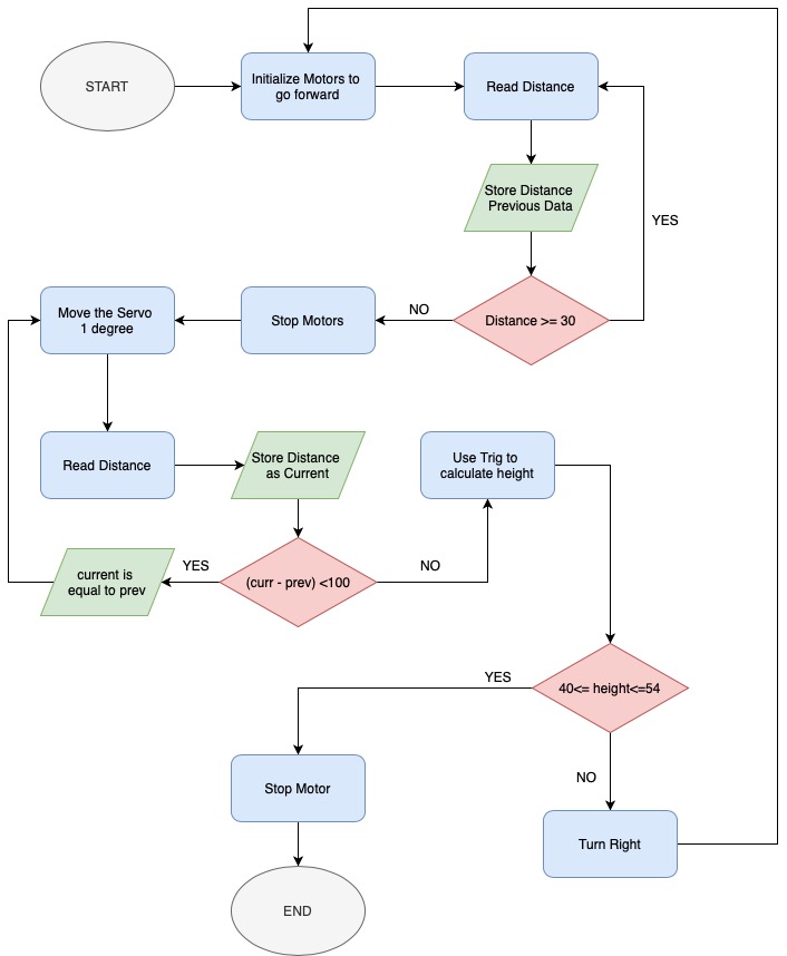
This diagram is a representation of the software implemented to navigate through the playing field using the time of flight, servo, and motors.
The software begins by setting the motors in the forward position and starting up the time of flight sensors. The sensor continuously takes values in order to detect objects in its path. As soon as it reads an object less than or equal to 30 mm, it stops the motor and begins to take a measurements. It increments one degree at a time until it has reached the top of the object.The last measurement taken before reaching above the object is used to calculate its height along with its corresponding angle. It compares the calculated height to the height of the object it is searching for then either turns right to continue its search if it does not match the value or stops the motors completely to indicate it has found the object it was looking for.
For the implementation of software, Switch Case Statements are utilized for its readability and structure and is easily modifiable. Each state is defined by an integer of a value between 0 to 3. The code begins with defining the states START, MEASURE, TURN and STOP and assigning them 0, 1, 2 and 3 respectively. The variable nextState is initialized as 0, therefore the robot always begins in the START state when it turns on. Each function then returns the nextState, which is another integer between 0 to 3. The switch case then cycles through the appropriate cases until it reaches the STOP state.
The following code demonstrates the Switch Case Statements utilized in the code.
void loop()
{
  int state = nextState;

  switch(state){
    case START:
      nextState = startState();
      break;
    case MEASURE:
      nextState = measState();
      break;
    case TURN:
      nextState = turnState();
      break;
    case STOP:
      nextState = stopState();
      break;
    default:
      Serial.println("ERROR WITH STD");
      break;
  }
Problems Encountered
Two major problems I encountered are listed below with their causes and solutions:
Problem #1: Robot turns right after start-up
Cause(s): Sensor glitches during initialization and begins to take readings that would indicate it should turn right.
Solution(s): Insert a delay during initializations to allow for the sensor to take a couple reading before the motors runs in the forward position.
Problem #2: Couldn't identify target object
Cause(s): Robot takes bad turns, which would read the box at a skewed angle. The target object would not be identified and robot would turn right.
Solution(s): Adjusted the timing on the turns to ensure it is a 90° turn and increased the target range after several readings of the target object.
References
- Proximity sensing - https://www.techopedia.com/definition/15003/proximity-sensor
- SparkFun Time of Flight Sensor - https://www.sparkfun.com/products/12785
- Arxterra 3DoT v7 Block Diagram - https://www.arxterra.com/classes/c-c-arduino-robots/reference-sheets/

