Mini-Rosco/Spring/2020
Mini-Rosco – GPS Tracking Testing
Author: Giann Bullo
Table of Contents
Introduction
The GPS module works using a constellation of satellites and ground stations. These satellites transmit information back to earth over radio frequency which ranges from 1.1 to 1.5 GHz. The information is then sent to a ground based GPS receiver which calculates the position and time. The data that is being sent contain pieces of information that allows the GPS receiver to accurately calculate its position and time. The accuracy of the position and time depend on if the GPS receiver can see at least 4 satellites.
Parts
- Arduino Uno
- 4 jumper wires
- Parallax Pam 7Q GPS Module
Testing
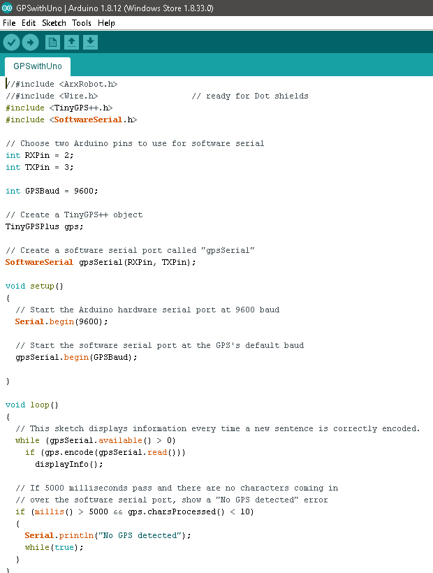
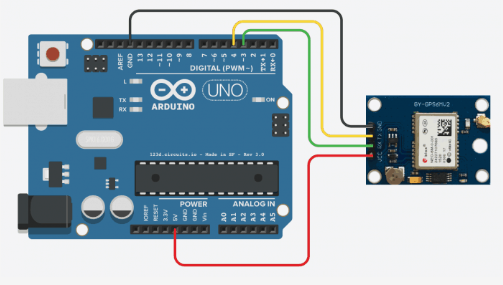
For testing I connected the Parallax Pam 7Q GPS Module to an Arduino Uno. Please note that the method used for acquiring the GPS information was NOT created by Mini-Rosco and all credit goes to Tiny GPS library and as such will not be listed in this blog post to avoid taking credit for another person’s original work. However, the method and algorithm used to implement this code with a compass to create a waypoint algorithn was created by Mini-Rosco. I uploaded code from the tiny GPS library that receives the latitude, longitude, altitude, date, and time. This info would be displayed on the serial monitor Arduino. By including the software serial code we were able to assign pins for the receiver and transmitter of the GPS module. Most of the code is the same from the example however the baud rate needed to be changed to 9600 to match with the GPS module baud rate. The baud rate specifies how fast data will be sent over the serial line. The value determines how long the transmitter will hold a serial line either high or low. If the value was lower or higher than 9600 the data would be encrypted. This error is due to the fact that the clocks and sampling periods can’t keep up.

Figure 2 – Picture of the Code for the GPS Breakout Board
Results
The acquisition took no less than 15 minutes when testing the GPS module at my house. At school, however, it took way longer and needed to be near a window to get the position and time. The reason for this is because there were too many obstructions such as the building. This factor created errors in the classroom location. It took around 20 minutes to get the position of the GPS and had a larger margin of error for the position.
Figure 3 – Serial Monitor acquires the correct information
The results of the code matched the position and time of where the GPS was located to some degree. When the longitude and latitude was checked on a website it was a few feet of its target. It would get the location with a 5 feet error margin. As we moved from location to location the GPS had an accuracy of 90%. The most accurate reading of our location comes from having a clear view of the sky without any obstructions. Within 30 seconds I was able to get a position of the GPS module down to +/– 5 meters. As I moved locations the accuracy was better compared to being inside a house or a building.
Conclusion
In conclusion, the GPS Module seemed to get the job done in terms of getting the exact position and time. The only problem with the GPS module was the acquisition of the position. Without a clear view of the sky it took too much time to receive the data. This has led us to reviewing our requirements for the PDR and CDR. The code will also need to be configured to receive data using the I2C pins since the RX and TX are being used on the 3Dot for Bluetooth. Other than that the GPS module is fully functional and can be used for the Mini-Rosco.
References
- https://learn.sparkfun.com/tutorials/gps-basics/all

