Fuzzy Bear/Spring/2020
PCB Design
Author/s: by Jaime Cortez
Table of Contents
Introduction
Fuzzy Bear is almost here and we’re pushing the limits of cuteness technology to give every child the adventure of a lifetime. To assist with this, Fuzzy Bear needs up to 11 servos to navigate itself through its environment and accomplish its mission. In this blog post, we’ll be discussing the bumps on the road Fuzzy Bear faced, such as the v1 demo issues, to enhance the overall electrical design. This, however, was just the beginning of its troubles and needed additional components such as the Adafruit Servo Shield to operate all its functional legs. It also needed a thermal shield to warm itself up and to give its owner warm fuzzy cuddles. This all sounds concerning when thinking about all the load Fuzzy Bear has to carry. This is why we’re pioneering the engineering of circuitry to adjust and resize the board by designing a custom PCB. Now let’s get started!
Breadboarding
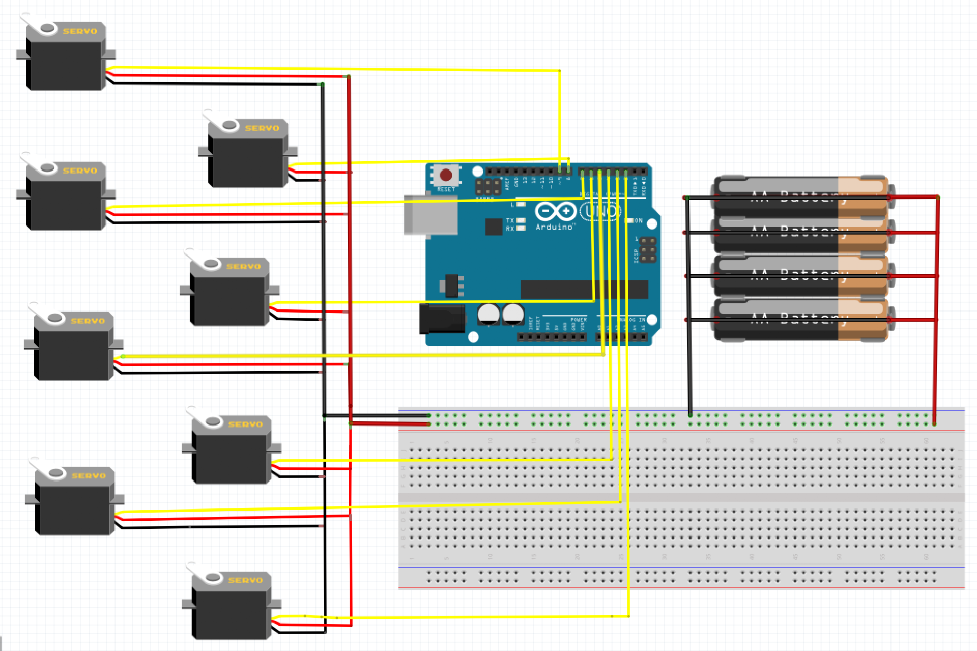
For the first prototype, Fuzzy Bear had a breadboard on its back and was powered through the Arduino Uno 5V pin. The circuit looked as shown below in the Fritzing diagram without the external battery pack. This prototype was prone to failure as Fuzzy Bear struggled to lift its own weight but it did however succeed in executing movement commands. Why didn’t this work? Considering that when the Arduino Uno is powered via USB cable, each pin can only output about 40 milliamps and the servos need several hundred milliamps to get Fuzzy Bear on its feet. This leads to the addition of the external battery supply as shown in the Fritzing diagram. With the battery pack, we were able to verify that the Arduino did in fact lack a lot of power. This new improvement led to the verification of the MG90 servos being strong enough to get Fuzzy Bear through a day’s worth of work.
PCB Design
In order for Fuzzy Bear to pass validation, it needs to be substantial, robust, and as adequate as can be. This is where the PCB can excel in the assistance of the overall electrical design. Using EagleCAD, the eagle cad file layout of the Adafruit Servo Shield was adjusted and resized to create a new shield for the 3dot board. The great thing about this board is that it only requires 2 pin connections to be communicating with the 3dot board with the I2C interface. Throughout the design process, many design issues occurred which required multiple iterations in order to achieve the best layout. Now let’s jump right into the PCB layout.
1st Iteration
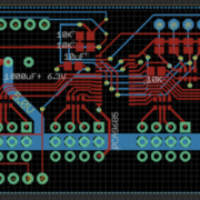
For the first iteration, we initialized the board dimensions and placed the header pins in the correct position to make it compatible with the 3dot board. From the schematic, we can see that this version contains the jumpers, PCA9685 IC, reverse voltage protection IC, an optional capacitor, and most importantly the pinouts for the servos. This design seemed perfect for Fuzzy Bear to power up all its legs but one major flaw came out of this design. The 3dot board has a battery that takes up a decent amount of space in addition to the towering height it obtains. This is an issue due to the fact that the PCB is going to be stacked on top and therefore won’t have enough height clearance between the board and the battery. The design had to be updated.
Other remarks that Professor Hill had mentioned were regarding the trace cursor size, the surface mount components size, and the resistor values that are in series with the LEDs. The cursor size is at a default 6 which is fine for most PCB manufacturing standards but this also leads to an increase in a defective PCB. Therefore the size needs to be at least 10 to be certain that this does not happen except for the power traces which need to be larger for more current to flow through. The SMT component size that Adafruit used were 805s but for convenience, 603s were recommended instead. As for the resistor value, it changed from 330 ohms to 1000 ohms to make it more power efficient. All of these corrections need to be considered in the 2nd design as we will show next.
2nd Iteration
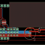
In the 2nd iteration, the first major change we can see is the battery cut out. Thanks to Sojourner from the previous year, Jaap was able to provide me with his team’s PCB dimensions with the verified cut out for the battery. The design from the 1st iteration required removing some unnecessary pins and components to get all of it to fit within these dimensions. This servo shield only needs 11 servos to function which is why we removed 4 pin servo connectors from the layout. Three of the jumpers that are needed to assign a unique address to the shield were also removed in the process since we’re only using two shields. As a result, the 2nd design is shown above that includes the adjustments of the issues mentioned previously.
Engineering is performed to better the already improved design which is why the 2nd iteration needs to be improved to give Fuzzy Bear its money’s worth. As mentioned by Chris, this design isn’t fully utilizing the ground planes to make it feasible to connect all the ground traces together without using the actual wire trace. This will clean up our design and free up space for future adjustments if needed. The 2nd design also creates some interference issues when connecting the servo wires to the pins once it’s time to stack the thermal shield. Professor Hill brought up the idea of moving the servo pins out onto the edge next to the battery to make the overall design more convenient. This allows the connections to be made without having to take off the thermal shield each time. The final design iteration takes all of this into consideration and is included in the final report.


