MicroFobo Spring 2020
MicroFobo: Circuit & PCB Design
Author: Jeffrey Macahilig
Table of Contents
Introduction
This generation of MicroFobo requires a custom printed circuit board(PCB) that controls eight servos, one stepper motor, and one Lidar. The PCB will also allow for the use of an external power supply to provide sufficient power to the servos and stepper motor. The board will be attached to a 3DoT board.
Breadboard Design
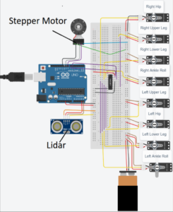
The breadboarding of the PCB is based on the previous generation of MicroFobo’s design. The CD4017 decade counter and servo connections were inherited and implemented into the breadboarding of this version of MicroFobo. The previous version of this robot was based on Renbotics use of the CD4017 decade counter. The design was tested before implementing more components to the future PCB using an Arduino UNO. After confirming that the design was working as intended, a lidar and stepper motor were added to the design.
The breadboard design was then ready to be designed onto a PCB designing software to get fabricated into a shield to attach onto the 3DoT Board. The software that was used to perform this custom board design was EagleCAD.
Eagle Design
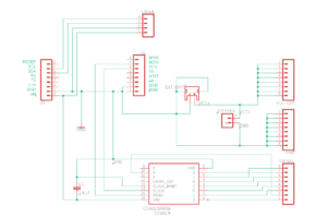
Figure 2 displays the schematic for the custom servoshield. It consists of the CD4017, pin headers for the servos, a JST mount for an external battery, and pin headers for the Lidar and stepper motor. The external battery is not connected to the CD4017 to prevent any noise to occur within the chip. The chip is solely connected to the 3DoT Board’s VM output pins. These components will be used to design a layout for the board fabrication.
Board Layout V1
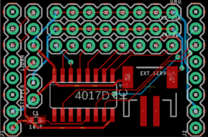
Figure 3 shows the first iteration of the custom PCB. This iteration of the PCB was created when first learning EagleCAD. It was not verified under any DRC and it did not contain any ground or power planes to reduce the amount of traces. This version of the board was difficult to decrease the amount of traces due to the placement of the CD4017 and JST mount for the external power for the servos. The lack of planes also caused long chains of traces which could easily be removed with the use of power and ground planes.
Final Board Layout
Figure 4 shows the final iteration of the board. When compared to figure 3, the CD4017 and JST mount swapped locations and polygon planes were added to reduce the number of traces. This version of the board was verified under SparkFun’s DRC, and some problems that were detected by the DRC were mostly trace clearances and via sizes. This board was approved and cleared for fabrication, and the files for the board were then submitted to JLCPCB for fabrication.
Board Fabrication
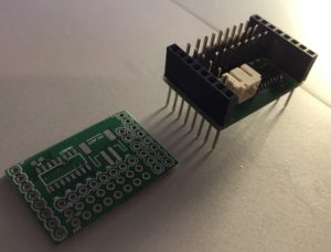
Figure 5 shows the PCB when it came from JLCPCB(left) and the components soldered onto that board(right). Instead of using breakaway headers for the connectors that connect onto the 3DoT board stacking headers were used. These headers were used because there was a lack of space on the PCB and some digital pins were required to operate the stepper motor.
Conclusion
This PCB design allows for the use of a Lidar and stepper motor. An issue that caused problems in laying out the components for fabrication was the size of the PCB. It left little room for moving certain components around and it caused the use of stacking headers instead of breakaway headers. EagleCAD was a great tool in creating the PCB and it allowed for easy fabrication with JLCPCB.


