Spring 2016: 3DoT David Board Troubleshooting
BY: Christopher Hirunthanakorn (Missions, Systems and Test Engineer)
Introduction:
After receiving the assembled 3DoT board that my project manager (Omar) and manufacturing engineer (Andrew) put together, tests were performed to make sure the board was functional. The basic firmware was uploaded by the assembly team, so that step was skipped. More information for uploading firmware to the 3DoT board can be found in Tae’s post for the 3DoT Goliath.
Related Requirements:
- The 3DoT David shall be a robot that demonstrates the capability of the new 3DoT micro-controller for DIY hobbyists.\
3DoT David Board Troubleshooting
There were four tests to check the functionality of the 3DoT board, which are listed below.
- 3DoT board can be turned on and off by using the switch.
- Arxterra App can connect to the 3DoT board via bluetooth.
- Two motors can be controlled by the 3DoT board.
- The battery can be recharged when a micro usb cable is connected as indicated by the LED.
After performing all of the tests, it was found that there was an issue with the motors. When a motor was connected to the motor A connection, it would operate normally. However, that same motor would not work for the motor B connection even though the code was driving both motor connections at the same speed.. It should be noted that this issue was also found on the 3DoT board that the 3DoT Goliath assembled.
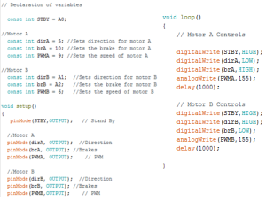
In order to address this issue, Tae, Nick, and I met up to troubleshoot the problem. The following code in order to test both motor connections at the same time.

The following test procedure was used to find the source of the problem.
Test Procedure:
- Take out the battery before testing using a multimeter
- Set the multimeter to measure resistance setting in the 100k ohm range
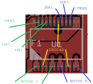
- Check for shorts on the TB6612FNG Dual Motor Driver Chip
- The measured impedance of any two pins should be much higher than the 100k ohm.
- If a value of 0 resistance or close is displayed, then there is a short.
- Plug the battery back in and turn on the 3DoT board.
- Measure the voltage across the motor terminals to make sure the correct voltages are outputted.
- Measure the voltage across the Atmega 32u4 pins that are connected to the TB6612FNG Dual Motor Driver Chip to make sure the correct voltages are outputted. Those pins are PB5, PB6, PC6, PD7, PF5, PF6, and PF7.
- Record results
The results of our test are as follows:
- There were no shorts on the TB6612FNG Dual Motor Driver Chip.
- We measured the expected 5 Volts at the motor A connection but no voltage was detected at the motor B connection.
- We measured 3.3 Volts for the motor A connections from the Atmega 32u4 pins but we measured 2.67 Volts for the motor B connections. We were unable to find out what was causing the motor B connections to have a different voltage than the expected 3.3 Volts.
Nick tried unsoldering and resoldering the dual motor driver chip but that had no effect on this problem. He told us that the possible causes of this issue could have been from the shipment of the parts, electrostatic discharge, heat, during assembly, etc. Because no solution was found, we informed Professor Hill about this issue and returned the 3DoT boards to be analyzed and repaired. We are currently using a Sparkfun Pro Micro as a replacement for demonstrations and testing.
Conclusion:
This experience showed the importance of testing all components that are purchased or received to make sure they are functioning properly. It also highlighted the importance of troubleshooting and establishing a procedure for testing and recording results.
Update: The 3DoT Board has been fixed and is fully functional.
Sources:

